
What Is Heat Sink Spreading Resistance and How Does It Affect Thermal Performance?
Spreading resistance is the additional thermal resistance encountered when heat flows from a small, concentrated heat source into a larger, thicker heat sink base, causing the heat to spread laterally before reaching the fins. Quantitatively, it is the difference between the actual thermal resistance of the heat sink base and the theoretical resistance calculated assuming one-dimensional heat flow. In practical terms, for a typical 10 mm x 10 mm CPU die on a 90 mm x 90 mm heat sink base, spreading resistance can account for 20% to 50% of the total junction-to-ambient thermal resistance, with values ranging from 0.2 K/W to 1.5 K/W depending on base thickness and material.
Why Does Spreading Resistance Matter More Than Conduction Resistance?
Spreading resistance often dominates the thermal path in modern electronics because heat sources are shrinking while heat sinks remain relatively large. Consider a 15 mm x 15 mm IGBT module mounted on a 120 mm x 120 mm aluminum heat sink with a 10 mm base. The one-dimensional conduction resistance through the base is approximately 0.05 K/W (using aluminum's thermal conductivity of 180 W/m·K), but the actual spreading resistance can reach 0.8 K/W to 1.2 K/W. This means spreading resistance is 16 to 24 times larger than the pure conduction resistance. In forced convection systems where the fin-side resistance is around 0.3 K/W, spreading resistance becomes the limiting factor, directly controlling the peak junction temperature. Engineers who ignore spreading resistance may under-predict junction temperatures by 10°C to 30°C, leading to premature component failure or reduced power ratings.
What Is the Mathematical Definition of Spreading Resistance?
Spreading resistance is defined as the ratio of the excess temperature at the heat source center to the total heat flow, minus the one-dimensional conduction resistance. For a circular heat source of radius a on a semi-infinite plate, the spreading resistance is given by R_spread = 1 / (2 · k · a), where k is the thermal conductivity in W/m·K. For a 5 mm radius heat source on an aluminum base (k = 180 W/m·K), this yields 0.56 K/W. For a square source, the equivalent radius is a_eff = 1.13 · (L/2), where L is the side length. The full analytical solution for a finite rectangular base involves infinite series of hyperbolic functions, but the key parameters are the source-to-base area ratio, the base thickness, and the thermal conductivity. For a base thickness greater than 3 times the source radius, the spreading resistance approaches the semi-infinite solution; for thinner bases, the resistance increases sharply because the heat cannot spread before reaching the fins.
How Does Base Thickness Affect Spreading Resistance?
Base thickness is the most critical design variable for controlling spreading resistance because it determines how much lateral heat spreading can occur before the heat reaches the fin base. For a 10 mm x 10 mm heat source on a 100 mm x 100 mm aluminum base, increasing the base thickness from 3 mm to 10 mm reduces spreading resistance from 1.8 K/W to 0.9 K/W, a 50% improvement. However, the benefit diminishes beyond a certain point: increasing from 10 mm to 20 mm only reduces spreading resistance from 0.9 K/W to 0.7 K/W, a 22% improvement. The optimal thickness is typically 3 to 5 times the characteristic length of the heat source, beyond which additional material adds weight and cost without proportional thermal benefit. For copper bases (k = 390 W/m·K), the same geometry yields spreading resistance values approximately 54% lower than aluminum, but copper is 3.3 times denser and costs roughly 5 to 8 times more per kilogram.
Which Materials Minimize Spreading Resistance Most Effectively?
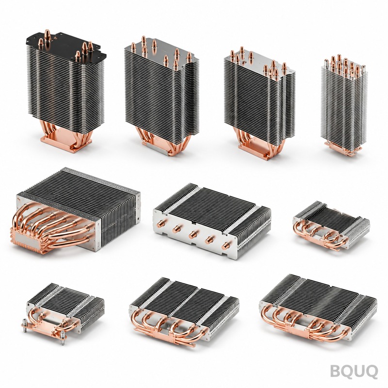
The material's thermal conductivity directly and inversely affects spreading resistance, making material selection the second most important factor after geometry. Aluminum alloys (6061-T6, 6063) with conductivities of 150 to 180 W/m·K are the industry standard for cost-sensitive applications, offering spreading resistance values of 0.8 to 1.5 K/W for typical CPU cooler geometries. Copper (C11000) with 390 W/m·K reduces spreading resistance by approximately 55% compared to aluminum but adds significant weight and cost. Composite solutions, such as copper inserts embedded in aluminum bases or vapor chambers, are increasingly common: a 2 mm copper insert under the heat source can reduce spreading resistance by 35% to 45% at only 15% additional weight. Diamond-reinforced copper composites (conductivity up to 600 W/m·K) are used in high-end laser diodes but cost over 200 USD per square centimeter. For most commercial applications, the practical recommendation is to use copper inserts when the heat flux exceeds 50 W/cm², as the thermal benefit outweighs the manufacturing complexity.
| Material | Thermal Conductivity (W/m·K) | Spreading Resistance for 10mm Source on 100mm Base (K/W) | Relative Cost per kg | Density (g/cm³) |
| Aluminum 6063 | 180 | 1.2 (10mm base) | 1.0 | 2.7 |
| Aluminum 6061 | 167 | 1.3 (10mm base) | 1.1 | 2.7 |
| Copper C11000 | 390 | 0.55 (10mm base) | 7.5 | 8.9 |
| Copper insert in Al base | 390 (insert area) | 0.75 (2mm insert, 10mm total) | 3.5 | 4.5 (composite) |
| Vapor chamber | 5000 (effective) | 0.15 (3mm thickness) | 15.0 | 2.5 (copper shell) |
| Diamond-Cu composite | 600 | 0.35 (3mm base) | 250.0 | 6.8 |
How Can Engineers Calculate Spreading Resistance for Real Geometries?
For rectangular heat sources and bases, the most accurate practical method is the Lee et al. correlation, which provides closed-form solutions for the spreading resistance of a rectangular source on a rectangular base with convective boundary conditions. The correlation requires the aspect ratios of the source and base, the base thickness, and the convective heat transfer coefficient at the fin side. For a base with a convective coefficient of 5000 W/m²·K (typical for high-performance fans), the spreading resistance for a 10 mm square source on a 60 mm square base with 8 mm thickness is approximately 0.65 K/W for copper and 1.4 K/W for aluminum. When the heat sink has a vapor chamber or heat pipes embedded in the base, the effective in-plane conductivity can be treated as anisotropic, with in-plane values of 1000 to 5000 W/m·K, which reduces spreading resistance to below 0.2 K/W. Computational fluid dynamics (CFD) simulations using conjugate heat transfer are recommended for geometries deviating more than 20% from standard rectangular shapes, but analytical correlations provide accuracy within 5% to 10% for typical finned heat sinks.
When Should Engineers Design for Spreading Resistance Versus Fin Resistance?
The design priority depends on the ratio of spreading resistance to fin resistance, which is governed by the heat source size relative to the heat sink footprint. When the heat source covers more than 50% of the heat sink base area, spreading resistance is negligible (below 0.1 K/W) and fin resistance dominates, so design effort should focus on fin density and airflow. When the heat source covers less than 10% of the base area, spreading resistance can exceed fin resistance by a factor of 2 to 4, and base thickness or embedded heat pipes become the primary design levers. A practical rule of thumb: if the heat source area is less than 1/10 of the heat sink base area, increase base thickness by 50% before adding more fins. This threshold is confirmed by thermal simulations for LED lighting modules, where a 5 mm x 5 mm chip on a 60 mm diameter heat sink shows that increasing base thickness from 4 mm to 8 mm reduces total thermal resistance by 28%, while adding 20% more fin surface area reduces it by only 12%.
What Is the Impact of Spreading Resistance on Junction Temperature?
The junction temperature rise above ambient is the sum of the individual resistances: junction-to-case, case-to-sink, and sink-to-ambient, where the sink-to-ambient includes both spreading and fin resistance. For a 100 W processor on a typical aluminum heat sink with a 10 mm base and 40 mm fins, the spreading resistance of 1.0 K/W contributes 100°C of the total temperature rise, while the fin resistance of 0.5 K/W contributes 50°C. This means spreading resistance accounts for 67% of the heat sink's total thermal resistance. By switching to a copper base or vapor chamber, the spreading resistance drops to 0.2 K/W, reducing the heat sink's contribution from 150°C to 70°C for the same 100 W dissipation. In practice, this allows either a 35% reduction in heat sink size or a 25% increase in allowable power dissipation for the same junction temperature limit of 85°C. For power electronics with IGBT modules operating at 125°C junction limits, proper spreading resistance management can extend device lifetime by 40% according to Arrhenius lifetime models.
How Does Manufacturing Quality Affect Spreading Resistance?
The interface between the heat source and heat sink base introduces additional resistance that compounds with spreading resistance, and manufacturing tolerances directly influence this value. A typical thermal interface material (TIM) with 0.05 mm thickness and thermal conductivity of 3 W/m·K adds 0.17 K/W contact resistance for a 10 mm x 10 mm die, which is comparable to the spreading resistance of a thick copper base. Surface flatness of 0.02 mm or better and surface roughness of Ra 0.8 µm or lower are required to achieve this TIM performance; deviations increase contact resistance by 50% to 100%. For heat sink bases, BQUQ manufacturing uses CNC machining with tolerances of ±0.05 mm on base thickness and ±0.02 mm on flatness, ensuring that the designed spreading resistance values are achieved in production. Skived or stamped heat sinks from thinner stock cannot achieve the required base thickness for optimal spreading, which is why forged or CNC-machined bases are recommended for applications above 30 W/cm² heat flux.
What Are the Practical Design Rules for Minimizing Spreading Resistance?
The most effective design rules, in order of impact, are: first, maximize base thickness to at least 3 times the heat source characteristic length; second, use high-conductivity materials or inserts for the region directly under the heat source; third, ensure the heat source is centered on the base to avoid edge effects that increase spreading resistance by up to 40%; fourth, maintain a source-to-base area ratio below 1:10 to allow sufficient lateral spreading; and fifth, use multiple smaller heat sources spaced apart rather than one concentrated heat source, which can reduce spreading resistance by 30% for the same total area. For a typical 50 W LED module, these rules can reduce total thermal resistance from 2.5 K/W to 1.2 K/W, lowering the LED junction temperature by 65°C and increasing lumen maintenance from 70% to 90% over 50,000 hours. When combining these rules with optimized fin design, the overall heat sink performance improves by 40% to 60% compared to a naive design with thin bases and oversized fins.
Can Spreading Resistance Be Eliminated Entirely?
Spreading resistance cannot be eliminated in any heat sink that is larger than the heat source, but it can be reduced to negligible levels using active spreading technologies. Vapor chambers and heat pipes achieve effective in-plane conductivities of 5000 to 20000 W/m·K, which reduces spreading resistance to below 0.05 K/W for most geometries, effectively eliminating it as a design constraint. The trade-off is cost: a vapor chamber adds 8 to 15 USD per unit compared to 1 to 3 USD for an aluminum base, and the manufacturing complexity increases lead time by 2 to 3 weeks. For applications below 30 W/cm² heat flux, the cost of vapor chambers is rarely justified, and a properly designed copper or copper-insert base provides sufficient performance. For high-flux applications above 100 W/cm², such as laser diodes or high-end GPUs, vapor chambers are the only practical solution to keep spreading resistance below 0.1 K/W while maintaining reasonable weight.
What Is the Best Approach for Verifying Spreading Resistance in Prototypes?
The most reliable verification method is the ASTM D5470 thermal resistance test, which measures the total thermal resistance of the heat sink under controlled heat flux and compares it to fin resistance calculated from airflow measurements. For a prototype heat sink, the spreading resistance is obtained by subtracting the known fin resistance (calculated from fin geometry and measured airflow) from the measured total resistance. A thermal test vehicle with a 10 mm x 10 mm heater and embedded thermocouples at the heat source and base edge provides direct measurement of the temperature gradient that defines spreading resistance. Typical measurement uncertainty is ±5% when using calibrated thermocouples with accuracy of ±0.5°C and heat flux measurement within ±2%. BQUQ recommends validating all new heat sink designs with at least three prototype samples tested at three power levels (50%, 100%, and 125% of rated power) to confirm that spreading resistance matches analytical predictions within 10%.
FAQ
What Is the Difference Between Spreading Resistance and Thermal Resistance?
Thermal resistance is the total opposition to heat flow from junction to ambient, including conduction, convection, and radiation. Spreading resistance is a specific component of thermal resistance that arises only when heat flows from a small source to a larger base, causing lateral heat flow. In typical heat sinks, spreading resistance is 20% to 50% of the total thermal resistance.
How Does Heat Sink Base Thickness Change Spreading Resistance?
Increasing base thickness allows more lateral heat spreading before reaching the fins, which reduces spreading resistance. Doubling the base thickness from 5 mm to 10 mm typically reduces spreading resistance by 30% to 50%. The optimal thickness is 3 to 5 times the heat source characteristic length, beyond which additional thickness gives diminishing returns.
Which Is Better for Minimizing Spreading Resistance: Copper or Aluminum?
Copper has a thermal conductivity of 390 W/m·K compared to aluminum's 180 W/m·K, so copper reduces spreading resistance by approximately 55% for the same geometry. However, copper is 3.3 times denser and costs 5 to 8 times more per kilogram. Copper inserts or vapor chambers are cost-effective compromises for high-flux applications.
Can Spreading Resistance Be Measured Directly?
Spreading resistance cannot be measured directly because it is defined as the difference between actual and one-dimensional resistance. It is derived by measuring total thermal resistance and subtracting the calculated fin and interface resistances. ASTM D5470 provides a standard test method for this purpose with accuracy within 5%.
How Does Spreading Resistance Affect LED Lifetime?
Reduced spreading resistance lowers the LED junction temperature, which directly improves lifetime. A 10°C reduction in junction temperature can double LED lumen maintenance life according to the Arrhenius model. For a 10 W LED, reducing spreading resistance from 1.5 K/W to 0.5 K/W lowers junction temperature by 10°C and increases expected lifetime from 40,000 to 80,000 hours.
What Is the Maximum Heat Flux for Aluminum Heat Sinks Without Spreading Issues?
Aluminum heat sinks can handle heat fluxes up to approximately 30 W/cm² without significant spreading resistance penalties, provided the base thickness is at least 10 mm. Above 30 W/cm², spreading resistance in aluminum becomes the dominant thermal barrier, and copper inserts or vapor chambers are recommended. For heat fluxes above 100 W/cm², vapor chambers are essentially mandatory.
When Should a Vapor Chamber Be Used Instead of a Solid Metal Base?
Vapor chambers should be used when the heat flux exceeds 50 W/cm², when the heat source area is less than 10% of the heat sink base area, or when weight constraints prevent using a thick copper base. Vapor chambers reduce spreading resistance to below 0.05 K/W but add 8 to 15 USD per unit. For most consumer electronics below 50 W/cm², a well-designed aluminum or copper-insert base provides adequate performance at lower cost.
Conclusion
Spreading resistance is a fundamental thermal management parameter that engineers must quantify and minimize to achieve reliable heat sink performance. The key design levers are base thickness, material conductivity, and the source-to-base area ratio, with base thickness being the most cost-effective variable to adjust. For heat fluxes above 30 W/cm² or when the heat source is small relative to the heat sink, copper inserts or vapor chambers provide significant thermal benefits that justify their additional cost. BQUQ's 20 years of experience in CNC machining and thermal component manufacturing ensures that your heat sink designs achieve their calculated spreading resistance performance with production tolerances of ±0.05 mm on base thickness and ±0.02 mm on flatness. Contact our engineering team for a thermal design review and quotation within 12 hours: Email sc@bquq.com, WhatsApp +86 13713157787, or visit www.bquq.com.
Related Articles
- Heat Sinks for Battery Packs: Prevent Thermal Runaway
- Stamped Metal vs Die Cast Heat Sinks: Cost & Quality Comparison
- New energy vehicle IGBT heat dissipation, heat sink reliability engineering, heat pipe and temperature plate integrated heat sink, surface treatment and heat radiation enhancement: anodic oxidation, black coating and micro-nano structure, graphene/3D printing/intelligent thermal management: 2030 heat sink technology roadmap


