
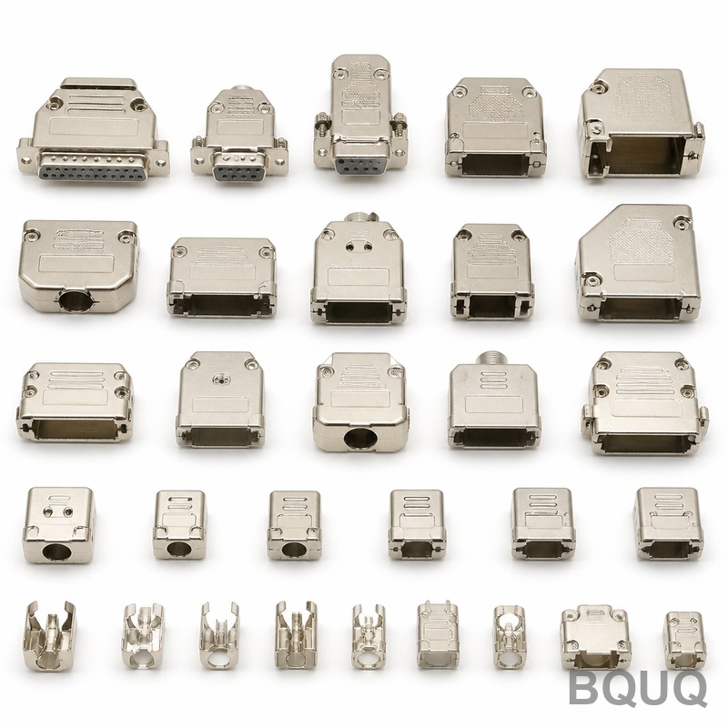
What Is Progressive Die Stamping and How Does It Work?
Progressive die stamping is a high-speed metal forming process where a coiled strip of metal is fed through a series of stations in a single die, with each station performing a distinct operation (cutting, bending, punching, or drawing) to produce a finished part in one pass. It works by synchronizing the strip’s indexed movement with the press stroke, allowing multiple operations to occur simultaneously on different portions of the strip. This method is ideal for high-volume production of small to medium-sized parts, achieving tolerances as tight as ±0.005 mm with production rates ranging from 200 to 1,500 parts per minute depending on material and part complexity.
What Are the Core Steps Inside a Progressive Die System?
The process begins with uncoiling a metal strip—typically 0.1 mm to 6.0 mm thick—and feeding it into a press equipped with a progressive die. The die contains multiple stations, each performing a specific operation: piloting (alignment), blanking, punching, bending, drawing, and final cutoff. The strip advances by a fixed pitch (the distance between stations) with each press stroke, and a pilot pin engages a pre-punched hole to ensure exact positional accuracy of ±0.003 mm. For example, a typical station sequence for a bracket part might be: station 1 punches pilot holes, station 2 trims the outline, station 3 forms a 90-degree bend, and station 4 cuts the part free from the strip.
The press speed is a critical parameter. For thin materials under 1.5 mm thickness, speeds of 400 to 800 strokes per minute (SPM) are common, while thicker materials (3.0 mm or more) are limited to 50 to 150 SPM to prevent tool overheating and material springback. The die material is usually D2 tool steel or powder metallurgy steel (e.g., ASP 23), hardened to 58–62 HRC, with carbide inserts used for high-wear zones like pilot holes. Lubrication is applied via a spray or roller system, typically using chlorine-free mineral oil at a flow rate of 0.5 to 2.0 liters per hour, to reduce friction and prevent galling.
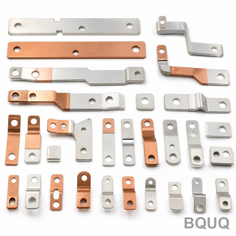
How Does a Progressive Die Differ from a Compound or Transfer Die?
A compound die performs multiple operations in a single press stroke at one station, whereas a progressive die distributes operations across multiple stations, each executed sequentially as the strip advances. Compound dies are faster for simple flat parts (e.g., washers) because all cutting happens at once, but they cannot handle parts requiring large bends or deep draws without repositioning. A transfer die, by contrast, uses mechanical fingers to move individual blanks from station to station, which allows for more complex 3D forming but at a slower speed (typically 20 to 60 parts per minute) and higher tooling cost.
Progressive dies are the preferred choice for parts that have a high length-to-width ratio or require tight dimensional consistency, such as lead frames for electronics, heat sink fins, or spring clips. The key advantage is that the strip itself acts as the carrier, eliminating the need for external part transfer and reducing cycle time. For instance, a progressive die for a connector terminal can produce 600 parts per minute, while a transfer die for the same part would only achieve 80 parts per minute. However, progressive dies are limited in their ability to form parts with undercuts or severe 3D contours, which often require a secondary operation or a transfer system.
Which Materials Are Best Suited for Progressive Die Stamping?
The process works with a wide range of metals, but the selection directly impacts tool life, speed, and cost. The most common materials are low-carbon steel (SPCC, DC01) for general hardware, stainless steel (SUS 301, SUS 304) for corrosion-resistant parts, aluminum alloys (5052, 6061) for lightweight heat sinks, and copper alloys (C1100, C17200 beryllium copper) for electrical contacts. Material hardness is the primary limiting factor: materials with a tensile strength above 600 MPa (e.g., high-carbon spring steel) will reduce die life by 30–50% due to increased wear on cutting edges.
For electrical applications, conductivity is critical. C1100 copper has a conductivity of 101% IACS and can be stamped at speeds up to 1,000 SPM, but its softness (hardness 40–50 HRB) requires sharper cutting edges and frequent die maintenance. Stainless steel SUS 301, with a tensile strength of 520 MPa in the annealed state, offers good formability but work-hardens rapidly, so dies must be designed with larger clearances (10–15% of material thickness) to prevent cracking. Aluminum 5052, with a density of 2.68 g/cm³, is excellent for heat sinks due to its thermal conductivity of 138 W/m·K, but its tendency to gall requires the use of anti-weld lubricants and polished die surfaces.
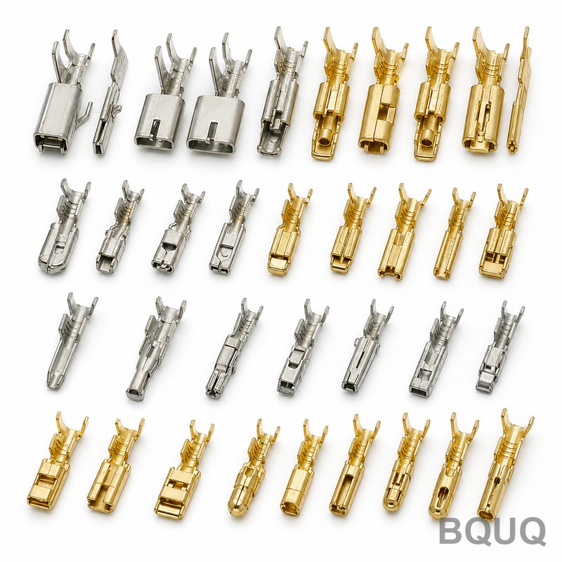
What Tolerances and Surface Finishes Can Be Achieved?
Progressive die stamping can hold tight tolerances, but the achievable values depend on material thickness, part geometry, and press rigidity. For flat blanked features, hole-to-hole tolerances of ±0.010 mm are possible with carbide dies and a precision press (C-frame or straight-side with minimal deflection). Bending tolerances are looser, typically ±0.05 mm to ±0.15 mm, because springback varies with material yield strength. For example, a 90-degree bend in 1.2 mm thick SUS 301 will spring back 2 to 4 degrees, requiring over-bending compensation in the die design.
Surface finish is determined by the blanking clearance and die condition. A clearance of 5–8% of material thickness for soft materials (aluminum, copper) produces a sheared edge with a burnish zone of 60–70% of the thickness and a surface roughness of Ra 0.8 to 1.6 µm. For harder materials (stainless steel), a clearance of 10–12% is used, resulting in a rougher edge (Ra 3.2 µm) but longer die life. If a fine-blanked edge is required (Ra 0.4 µm), a separate fine blanking process must be used, which adds 20–30% to the part cost. Burr height is typically controlled to less than 5% of material thickness, e.g., a 0.1 mm burr for a 2.0 mm thick part.
How Much Does Progressive Die Tooling Cost and What Is the Lead Time?
Tooling cost for a progressive die ranges from $3,000 for a simple 3-station die for thin aluminum to $80,000 or more for a 20-station carbide die for complex stainless steel parts. The cost is driven by the number of stations, die material, and precision requirements. A typical mid-range die for an automotive bracket (12 stations, D2 tool steel) costs $15,000 to $25,000 and has a lead time of 6 to 8 weeks. High-precision dies for electronics (16–20 stations, carbide inserts) cost $30,000 to $50,000 with a lead time of 10 to 12 weeks.
Die life varies with material and maintenance. A D2 steel die stamping SPCC steel can produce 500,000 to 1,000,000 strokes before needing sharpening, while the same die stamping SUS 304 will last only 150,000 to 300,000 strokes. Carbide dies last 3 to 5 times longer but cost 2 to 3 times more. It is important to note that tooling cost is amortized over the production volume; for volumes above 100,000 parts, progressive die stamping is almost always the lowest cost per part, often $0.02 to $0.10 per part, excluding material. For volumes below 10,000 parts, a CNC machining or laser cutting approach is more economical.
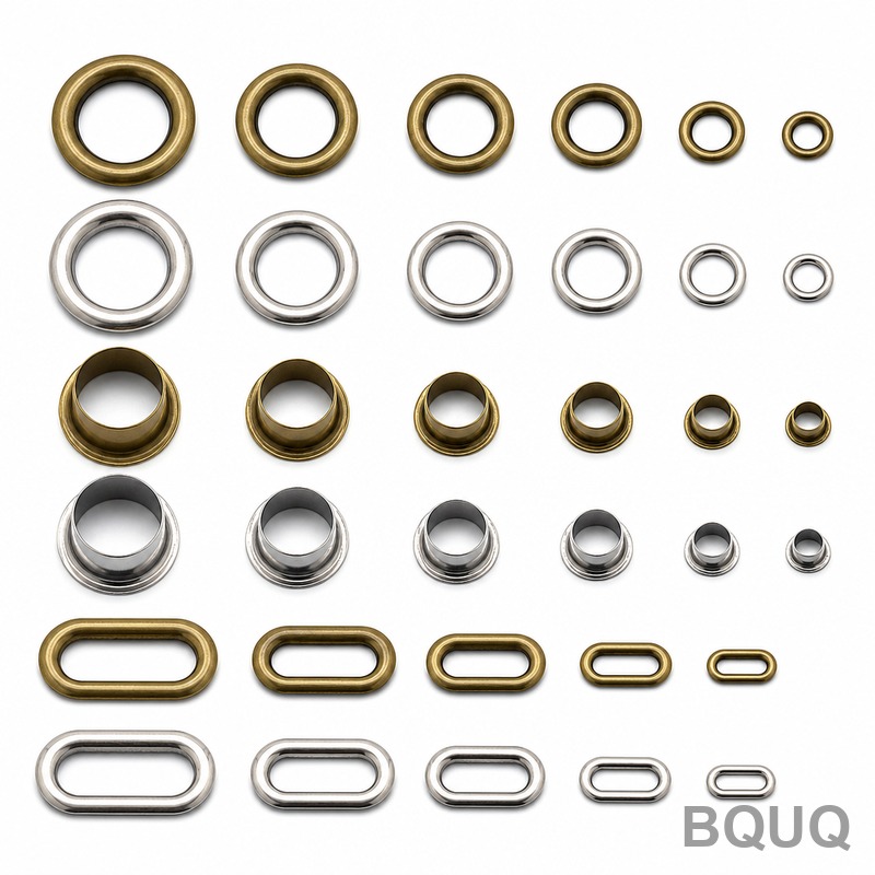
When Should You Choose Progressive Die Stamping Over Other Manufacturing Methods?
Progressive die stamping is the right choice when the part volume exceeds 50,000 units per year, the part is smaller than 300 mm in any dimension, and the geometry can be achieved with 2D or simple 3D forming (bends, lances, embosses, and shallow draws). It is the standard process for automotive clips, electrical terminals, heat sink fins, and metal springs. If the part requires a deep draw (depth greater than 1.5 times the diameter), a dedicated draw die or a transfer die is more suitable, as progressive dies struggle with material thinning and wrinkling in deep draws.
The process is also chosen for its repeatability. A well-maintained progressive die can produce parts with a dimensional consistency (CpK) of 1.67 or better, meaning less than 0.6 parts per million are out of tolerance. This consistency eliminates the need for 100% inspection, which is a major cost saving. However, if the part design is still evolving, the high initial tooling cost makes progressive stamping risky; in that case, prototyping with CNC machining or 3D printing is recommended before committing to a production die.
What Are the Common Defects in Progressive Die Stamping and How Are They Prevented?
The most frequent defects are burrs, springback, and galling. Burrs occur when the cutting clearance is too large or the die edges are worn; they are prevented by maintaining a clearance of 5–8% of material thickness and resharpening dies every 100,000 to 300,000 strokes. Springback, which causes bends to open up, is compensated by over-bending the die angle by 2–5 degrees or using coining (a secondary impact) to set the material. Galling, the transfer of material to the die surface, is prevented by using proper lubrication (viscosity 20–40 cSt at 40°C) and surface treatments like TiN coating on the die, which reduces friction by 50%.
Another defect is strip distortion, often caused by unbalanced forces from asymmetric stamping. This is mitigated by designing the strip layout to balance the cutting forces and using guide pins with a tolerance of ±0.002 mm. Material thickness variation (e.g., a 1.5 mm coil that varies by ±0.05 mm) can cause inconsistent forming; this is addressed by using tight-tolerance coils (ASTM A568 for steel) and adding a thickness sensor with feedback to the press. For high-speed stamping, heat buildup can cause die expansion and dimension drift; a straight-side press with forced oil cooling can maintain die temperature within ±5°C, ensuring stable part dimensions.
How Does Part Cost Scale with Volume and Material Utilization?
Part cost is dominated by material utilization, which is the ratio of part weight to the weight of the strip consumed. For a well-designed progressive die, material utilization ranges from 60% to 85%, depending on the nesting of parts on the strip. For example, a rectangular bracket can achieve 75% utilization if parts are nested at an angle or interlocked, while a complex shape with large cutouts may only achieve 50%. Material cost for SPCC steel is approximately $0.80 per kg, so a 10 g part uses 13.3 g of strip at 75% utilization, costing $0.011 for material. At a volume of 500,000 parts, this adds up to $5,500 in material savings compared to a 55% utilization design.
The table below summarizes typical production parameters for common materials:
| Material | Typical Thickness (mm) | Max Speed (SPM) | Achievable Tolerance (mm) | Die Life (strokes) | Relative Tooling Cost |
| SPCC steel | 0.5 – 3.0 | 800 | ±0.010 | 800,000 | 1.0x |
| SUS 304 stainless | 0.3 – 2.5 | 400 | ±0.015 | 250,000 | 1.5x |
| Aluminum 5052 | 0.5 – 4.0 | 1000 | ±0.008 | 1,000,000 | 0.8x |
| Copper C1100 | 0.2 – 2.0 | 1200 | ±0.005 | 600,000 | 1.2x |
| Beryllium copper C17200 | 0.1 – 1.0 | 900 | ±0.005 | 400,000 | 2.0x |
These figures assume a 15-station die, a 110-ton press, and standard lubrication. Actual values will vary with part geometry and press condition.
What Are the Key Design Rules for a Progressive Die Part?
To maximize manufacturability and minimize cost, a part should be designed with a consistent wall thickness, a minimum feature size of at least 0.8 times the material thickness for holes, and a minimum bend radius of 0.5 times the material thickness for soft materials and 1.0 times for harder materials. The distance between a hole and a bend should be at least 2 times the material thickness to prevent distortion. Avoid tight tolerances on bend dimensions unless absolutely necessary, as each ±0.01 mm tolerance increase will raise tooling cost by 5–10%.
Another rule is to minimize the number of forming operations by combining bends in the same direction whenever possible. For example, a U-shaped bracket requires two 90-degree bends that can be done in one station, but if the bends are in opposite directions, they need two stations, adding 10–15% to the die cost. Also, design the strip layout with a carrier strip width of at least 1.5 times the material thickness to ensure smooth feeding and prevent buckling. For parts with sharp corners, add a radius of at least 0.3 mm to avoid stress concentrations that cause cracking during stamping.
How Fast Can I Get a Quote for a Progressive Die Stamping Project?
At BQUQ, we provide a preliminary quote within 12 hours of receiving your part drawings (PDF, STEP, or IGES) and estimated annual volume. For complex parts requiring die design consultation, a detailed quote with tooling breakdown and per-part pricing is delivered within 2 business days.
What Is the Minimum Order Quantity for Progressive Die Stamping?
For progressive die stamping, the minimum order quantity is typically 20,000 parts per year, as the tooling cost must be spread over a sufficient volume to make the per-part cost competitive. For lower volumes, we recommend using CNC machining or wire EDM for prototype runs of 1 to 5,000 parts.
Can Progressive Die Stamping Handle Parts with Threads or Inserts?
Threads and inserts cannot be formed in the progressive die itself; they are added as secondary operations after stamping. Tapping is possible at 200 parts per hour using a tapping station, and heat-set inserts can be pressed in at 500 parts per hour, but these operations add $0.005 to $0.02 per part.
How Does Progressive Die Stamping Compare to Metal Injection Molding?
Progressive die stamping is faster (200–1,200 parts per minute vs. 10–50 parts per hour for MIM) and has lower tooling cost for simple 2D parts. However, MIM can produce complex 3D shapes with undercuts that are impossible to stamp, though it has higher per-part cost and a longer lead time for sintering.
What Maintenance Is Required for a Progressive Die?
Preventive maintenance includes daily cleaning of the die surface, checking the pilot pins for wear every 50,000 strokes, and resharpening the cutting edges every 100,000 to 300,000 strokes depending on material. A full die inspection and reconditioning is recommended every 500,000 strokes, costing 5–10% of the original die price.
Can Progressive Die Stamping Be Used for Heat Sinks?
Yes, progressive die stamping is widely used for heat sink fins made from aluminum 1050 or 6061, with thicknesses of 0.3 to 1.0 mm. The fins are lanced and bent to create the fin array, achieving a fin density of up to 15 fins per inch with a tolerance of ±0.05 mm, and the process produces 300–500 parts per hour.
What Is the Maximum Part Size for Progressive Die Stamping?
The maximum part size is typically 300 mm x 300 mm, limited by the press bed size and the strip width (up to 600 mm). For larger parts, such as automotive body panels, a transfer die or tandem press line is used instead, as the strip would be too stiff to feed accurately.
Progressive die stamping remains one of the most efficient and cost-effective methods for high-volume metal part production, offering unmatched speed, repeatability, and precision. The key to success is a thorough design review to ensure the part is optimized for the process, balancing tolerances, material selection, and tooling investment. With over 20 years of experience in CNC machining, stamping, and heat sink fabrication, BQUQ can guide you from prototype to full-scale production, ensuring your parts meet the highest quality standards. For a fast, accurate quote, contact our engineering team at sc@bquq.com or via WhatsApp at +86 13713157787. Visit our website at www.bquq.com to learn more about our capabilities and request a free DFM analysis.
Related Articles
- Intelligent online inspection and closed-loop quality control: creating a zero-defect production line for stamped parts
- Stamping digital factory and simulation-driven design: from virtual prototype to digital twin operation
- High-speed precision stamping and in-die microforming technology: from electronic connections to micromotor cores


