
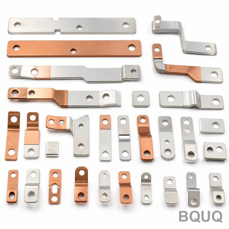
What Precision Can You Expect From Metal Stamping Tolerances?
For standard metal stamping, you can expect a dimensional tolerance of ±0.13 mm (±0.005 in) for blanking and forming operations, with precision fine-blanking achieving ±0.025 mm (±0.001 in) on critical features. Material thickness, tooling quality, and press speed are the primary variables that will either tighten or loosen these baseline figures. This guide provides exact data for stamping tolerances, tooling costs, and lead times so you can design parts that are manufacturable without overpaying for unnecessary precision.
What Is the Standard Tolerance Range for Metal Stamping?
The industry-standard tolerance for metal stamping is typically ±0.13 mm for hole-to-hole spacing and ±0.08 mm for bend-to-hole dimensions. For high-volume progressive die stamping, the practical limit for most features is ±0.05 mm, while fine blanking can hold ±0.025 mm on sheared edges. Parts requiring tighter than ±0.025 mm should be considered for secondary machining, as the cost of stamping tooling increases by roughly 30% for every 0.025 mm of added precision. For reference, material thickness up to 1.5 mm is the sweet spot for holding tight tolerances; thicker materials (above 3.0 mm) will naturally increase tolerance drift to ±0.20 mm or more.
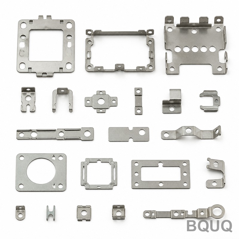
How Does Material Thickness Affect Stamping Precision?
Material thickness directly influences springback, which is the primary cause of tolerance deviation in bending operations. For steel thicknesses up to 1.2 mm, springback compensation can be predicted within ±0.05 mm, but for thicknesses above 3.0 mm, springback becomes unpredictable, requiring trial-and-error tooling adjustments that add 2 to 3 weeks to the development cycle. Harder materials like stainless steel 301 (full hard) exhibit 2 to 3 times more springback than mild steel DC01, so expect tolerances to widen by 50% when switching from mild steel to stainless. For precision applications, we recommend using material with a consistent hardness specification (e.g., HRB 70-80) because hardness variation alone can shift bend angles by ±1.5 degrees.
Which Stamping Processes Achieve the Tightest Tolerances?
Fine blanking is the most precise stamping process, achieving tolerances of ±0.025 mm on hole diameters and ±0.05 mm on flatness across the entire part. Progressive die stamping is second, with typical tolerances of ±0.05 mm to ±0.10 mm for features in the same die station, but cross-station tolerances (features made in different stations) will fall to ±0.15 mm due to strip feeding errors. Compound blanking (single-stroke, all features simultaneous) offers ±0.05 mm consistency but is limited to parts smaller than 150 mm x 150 mm. For comparison, a standard punch and die set for simple blanking will give ±0.13 mm, which is acceptable for most brackets and mounting plates.
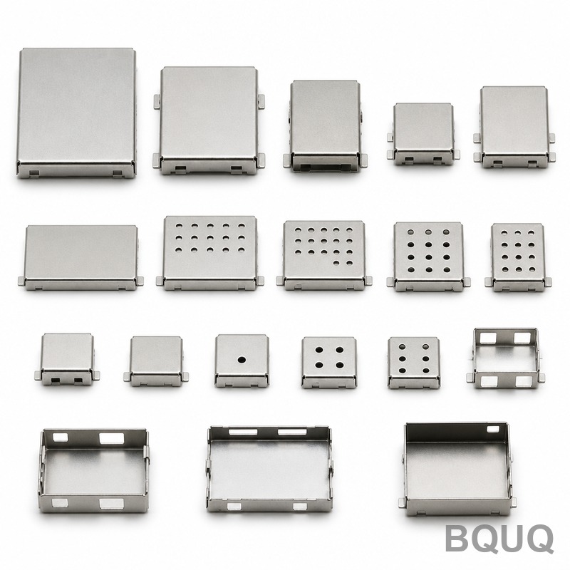
What Are the Tolerance Limits for Hole Diameter and Hole Spacing?
For pierced holes, the minimum hole diameter is generally 1.0 times the material thickness, and the hole tolerance is ±0.05 mm for diameters under 10 mm. Hole-to-hole spacing (center to center) is held to ±0.08 mm within the same die station, but this drifts to ±0.15 mm if the holes are in different stations. Edge-to-hole distance must be at least 1.5 times the material thickness to prevent distortion; below this, the hole will elongate by 0.10 mm to 0.20 mm. The table below summarizes typical tolerances by feature type for a 1.0 mm thick mild steel part:
| Feature Type | Standard Tolerance | Precision Tolerance | Typical Cost Premium |
| Hole diameter (pierced) | ±0.10 mm | ±0.05 mm | +15% |
| Hole-to-hole spacing | ±0.13 mm | ±0.08 mm | +20% |
| Bend angle | ±1.0 degree | ±0.5 degree | +25% |
| Formed feature height | ±0.15 mm | ±0.08 mm | +18% |
| Flatness (per 100 mm) | ±0.30 mm | ±0.10 mm | +30% |
| Blanked edge profile | ±0.13 mm | ±0.025 mm (fine blanking) | +40% |
How Much Does Tighter Stamping Tolerance Cost in Tooling?
Tooling cost scales non-linearly with tolerance requirements. A standard progressive die for a mid-sized bracket (100 mm x 80 mm) with ±0.13 mm tolerances costs between $8,000 and $15,000. Upgrading to ±0.05 mm on all features raises the die cost to $18,000 to $30,000 due to the need for precision guide pins, hardened tool steel (D2 or M2), and additional die stations for coining. Fine blanking tooling starts at $25,000 and can exceed $60,000 for complex parts, making it economical only for volumes above 100,000 parts per year. Per-part cost impact is smaller: moving from ±0.13 mm to ±0.05 mm typically adds $0.02 to $0.08 per part, depending on volume, while fine blanking adds $0.05 to $0.15 per part.
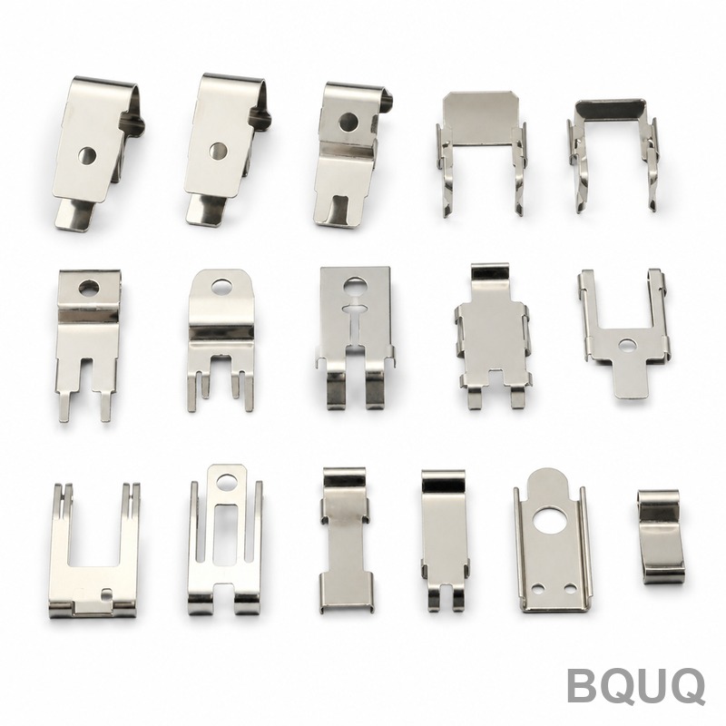
How Can You Design for Realistic Stamping Tolerances?
To avoid unnecessary cost, designate only 2 to 3 critical features on your drawing with tight tolerances (e.g., ±0.05 mm), and leave all other dimensions at the standard ±0.13 mm. Engineers often over-specify tolerances on every dimension, which forces the toolmaker to use higher-grade materials and additional finishing steps, increasing tooling cost by 40% to 60% without functional benefit. Also, avoid placing tight tolerance holes closer than 2.5 times material thickness from a bend line; the bend radius zone has localized thinning and work hardening that will distort hole geometry by up to 0.15 mm. Instead, position holes after bends (via secondary piercing) or move them at least 6.0 mm away from the bend apex.
Why Does Stamping Tolerance Drift Occur During High-Volume Production?
Tool wear is the primary cause of tolerance drift: a carbide punch used for piercing will wear 0.01 mm per 100,000 strokes, causing hole diameters to shrink progressively. For a run of 500,000 parts, a hole that started at 5.00 mm may end at 4.95 mm, exceeding the ±0.05 mm tolerance. Press thermal expansion also contributes; after 2 hours of continuous operation at 200 strokes per minute, the die temperature rises by 15 to 20 degrees Celsius, expanding the tool steel by roughly 0.02 mm per 100 mm of die length. To maintain tolerances over long runs, schedule tool maintenance every 50,000 strokes, use carbide inserts for piercing punches, and run the press at a consistent speed to minimize thermal cycling.
What Is the Lead Time for Precision Stamping Tooling?
A standard progressive die with ±0.13 mm tolerances takes 4 to 6 weeks from design approval to first articles. Adding precision requirements (±0.05 mm) extends this to 6 to 8 weeks due to additional simulation (finite element analysis for springback) and trial iterations. Fine blanking tooling requires 8 to 12 weeks because the tool design must account for V-ring configuration and hydraulic clamping forces. Rapid prototyping using 3D-printed dies for low-volume validation (up to 500 parts) can be done in 5 to 7 days but will only hold ±0.20 mm tolerances, so this is suitable only for form-fit testing, not production validation.
FAQ
Can Metal Stamping Hold Tolerances Below ±0.01 mm?
No, standard metal stamping cannot reliably hold tolerances below ±0.01 mm because of material thickness variation, tool wear, and press deflection. If you require sub-0.01 mm precision, plan for a secondary operation such as CNC machining or lapping after stamping. These operations add $0.10 to $0.50 per part but are the only reliable way to achieve micron-level accuracy.
How Do I Specify Tolerances on My Stamping Drawing?
Use geometric dimensioning and tolerancing (GD&T) symbols for critical features, and apply standard ±0.13 mm for all other dimensions. Call out only 2 to 3 critical dimensions with tighter tolerances, and specify material hardness range (e.g., HRB 70-80) to reduce variation. Always include a note that all tolerances are for parts measured at 20 degrees Celsius.
What Is the Difference Between Stamping and Fine Blanking Tolerance?
Stamping produces a sheared edge with a burnish zone and fracture zone, limiting tolerance to ±0.13 mm on edge profiles. Fine blanking uses a V-ring indenter and counter-pressure to create a fully sheared, smooth edge, achieving ±0.025 mm tolerance. Fine blanking also maintains flatness of ±0.05 mm per 100 mm, which is 6 times better than standard stamping.
When Should I Use Secondary Machining Instead of Tight Stamping Tolerances?
Use secondary machining when your tolerance requirement is below ±0.025 mm, when you need a specific surface finish (Ra below 1.6 micrometers), or when the feature geometry cannot be achieved by stamping (e.g., undercuts or threads). A good rule is to machine only the critical features, leaving the stamped blank as the main geometry. This hybrid approach reduces machining time by 70% compared to machining the entire part from solid.
Which Materials Are Easiest to Stamp with Tight Tolerances?
Low-carbon steels (DC01, SPCC) and aluminum alloys (5052, 6061) are the easiest to stamp with tight tolerances because they exhibit predictable springback. Stainless steel (304, 316) and titanium require 30% to 50% wider tolerances due to high springback and work hardening. Copper and brass are intermediate, offering good formability but requiring frequent tool polishing to maintain edge quality.
How Does Press Speed Affect Stamping Precision?
Press speed above 300 strokes per minute reduces tolerance accuracy by up to 40% because of increased vibration and reduced time for material flow. For parts with tolerances tighter than ±0.08 mm, run the press at 100 to 150 strokes per minute. Slower speeds also reduce die temperature rise, keeping thermal expansion below 0.01 mm.
Can I Get a Tolerance Report with My Stamping Parts?
Yes, BQUQ provides a full dimensional inspection report using coordinate measuring machine (CMM) data with a measurement uncertainty of ±0.005 mm. For every production batch, we sample 5 parts and report all critical dimensions against your drawing. We can also provide statistical process control (SPC) charts for high-volume runs over 50,000 parts.
Conclusion
Metal stamping is a highly precise manufacturing process, but the achievable tolerance is always a trade-off between cost, tooling complexity, and production volume. For most applications, standard tolerances of ±0.13 mm are sufficient and cost-effective; reserve ±0.05 mm or finer tolerances for critical functional features only. By communicating your true tolerance needs clearly and understanding the limits of the process, you will achieve faster lead times, lower tooling costs, and parts that meet your engineering requirements on the first try.
For an accurate tolerance assessment of your specific part design, send your 2D drawing or 3D model to our engineering team. We provide free design-for-manufacturability feedback and a firm quote within 12 hours. Contact us at sc@bquq.com, WhatsApp +86 13713157787, or visit www.bquq.com.


