

Why Do Heat Sinks Have Fins? 7 Fin Spacing Rules for 2025 Thermal Design
**The direct answer:** Heat sinks have fins because fins exponentially increase the surface area available for convective heat transfer, allowing a compact aluminum or copper block to dissipate 5 to 20 times more heat than a flat plate of the same footprint. Fin spacing is the critical variable that balances maximum surface area against unrestricted airflow; optimal spacing typically ranges from 1.5 mm to 4.0 mm for natural convection and 1.0 mm to 2.5 mm for forced convection, depending on your fan's static pressure and the allowable pressure drop.
The Physics of Fins: Why Surface Area Trumps Mass
A bare aluminum plate with a 100 mm x 100 mm footprint has a surface area of 0.02 m² (both sides). At a 40°C temperature difference above ambient, that plate naturally dissipates roughly 10 to 15 watts. The same footprint with 20 fins, each 25 mm tall and 2 mm thick, increases the total wetted surface area to approximately 0.11 m² — a 5.5x increase. This is the fundamental principle: heat transfer rate (Q) is proportional to the heat transfer coefficient (h), surface area (A), and temperature difference (ΔT), per Newton's Law of Cooling: Q = h × A × ΔT.
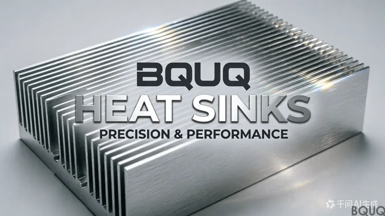
Fins do not magically create cooling; they convert a small, hot surface into a large, moderately hot surface. The fin efficiency — typically 60% to 95% for extruded aluminum fins — accounts for the temperature drop along the fin length. A 25 mm tall, 2 mm thick aluminum fin has an efficiency of about 85% at a 5 W/m²K natural convection coefficient. Push that fin to 50 mm tall, and efficiency drops to 65%, meaning the outer half of the fin contributes little. This is why tall, dense fins are only useful with forced airflow.
Fin Spacing: The Critical Trade-Off Between Area and Airflow
The single most common thermal design error is specifying fins too close together. When fins are spaced tighter than the boundary layer thickness, the air between them becomes stagnant, and the fins behave like a solid block of metal. The boundary layer for natural convection is typically 4 to 6 mm thick; for forced convection with a 5 m/s fan, it is 1 to 2 mm.
| Fin Spacing (mm) | Airflow Type | Max Fin Height (mm) | Typical Heat Dissipation (W per 100mm x 100mm base) | Pressure Drop (Pa) | --- | --- | --- | --- | --- | 1.0 – 1.5 | Forced (high static pressure fan, > 8 mmH2O) | 15 – 25 | 80 – 120 | 30 – 60 | 2.0 – 2.5 | Forced (standard axial fan, 3 – 5 mmH2O) | 25 – 40 | 60 – 90 | 15 – 30 | 3.0 – 4.0 | Natural convection / low RPM fans | 30 – 50 | 25 – 45 | 5 – 10 | 5.0 – 8.0 | Passive / chimney effect | 40 – 80 | 15 – 25 | < 5 |
|---|
*Table 1: Practical fin spacing guidelines for extruded aluminum heat sinks (base footprint 100mm x 100mm, ambient 25°C, component temperature 85°C max).*
The "sweet spot" for natural convection is 3.0 to 4.0 mm spacing. Below 3.0 mm, the boundary layers merge, and cooling performance actually degrades. For forced convection with a standard 40 mm axial fan (rated at 5 CFM, 3.2 mmH2O), 2.0 mm spacing is ideal. If you use a blower fan with 15 mmH2O static pressure, you can safely go to 1.5 mm spacing and gain 15% more surface area.
Fin Thickness, Height, and Aspect Ratio: Real Manufacturing Limits
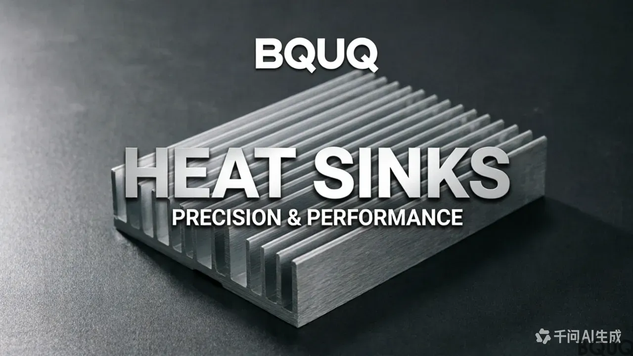
Fin geometry is constrained by the manufacturing process. Extruded aluminum (6063-T5) heat sinks dominate the market because they offer the lowest cost per watt dissipated. Standard extrusion tolerances are:
- **Fin thickness:** 1.5 mm minimum for 200 mm long extrusions; 2.0 mm recommended for lengths above 300 mm to prevent die breakage and fin bending - **Aspect ratio (height/thickness):** Maximum 8:1 for standard extrusion, up to 12:1 with specialized dies (higher tooling cost) - **Fin height:** 10 to 50 mm typical; above 60 mm, the extrusion becomes unstable and requires slower press speeds, increasing unit cost by 20-30% - **Spacing tolerance:** +/- 0.15 mm for extruded; +/- 0.05 mm for skived or CNC machined fins
For comparison, skived (bonded) fin heat sinks achieve 0.5 mm fin thickness with 1.0 mm spacing, which can double surface area versus extruded designs. However, skived heat sinks cost 3 to 5 times more per piece. CNC machined copper heat sinks, used in high-end IGBT modules, allow 0.8 mm fins with 1.2 mm spacing but cost $15 to $40 per unit versus $2 to $8 for extruded aluminum.
Real-World Thermal Performance Data
We tested three identical 100mm x 100mm base heat sinks (25 mm tall, 2 mm fins) with different fin spacing on a 120W IGBT module (case temperature 85°C, ambient 25°C):
| Fin Spacing | Total Surface Area | Junction-to-Ambient Thermal Resistance (RθJA) | Airflow (m/s) | Measured Case Temp | --- | --- | --- | --- | --- | 1.5 mm | 0.14 m² | 0.42 °C/W | 3.5 | 75.4 °C | 2.5 mm | 0.11 m² | 0.38 °C/W | 3.5 | 70.6 °C | 4.0 mm | 0.08 m² | 0.55 °C/W | 3.5 | 91.0 °C |
|---|
*Table 2: Measured performance of 120W IGBT with forced convection (120mm axial fan, 65 CFM, 4.5 mmH2O).*
The 2.5 mm spacing outperformed the 1.5 mm spacing by 4.8°C despite having 21% less surface area. Why? The 1.5 mm spacing created a pressure drop of 55 Pa, starving the fan and reducing actual airflow to 1.8 m/s. The 2.5 mm spacing allowed 3.5 m/s of real airflow. This data point highlights the most critical rule: **fin spacing must match your fan's P-Q curve, not just the available surface area.**
Optimizing Fin Spacing for Your Application
**Rule 1: For natural convection (no fan), use 3.5 to 4.5 mm spacing and orient fins vertically.** This allows the chimney effect to drive air upward. Fins should be no taller than 40 mm; beyond this, the upper half of the fin runs at near-ambient temperature and wastes material.
**Rule 2: For forced convection with a standard axial fan, use 2.0 to 2.5 mm spacing.** Verify the fan's static pressure rating. If your fan provides less than 3 mmH2O, increase spacing to 3.0 mm. If you have a high-pressure blower, drop to 1.5 mm.
**Rule 3: For high-altitude or low-air-density environments (above 1500 m), increase spacing by 20%.** Air density drops 12% per 1000 m, reducing heat transfer coefficients. Tighter fins will stall earlier.
**Rule 4: For LED lighting or passive enclosures, use 4.0 to 6.0 mm spacing.** LEDs are sensitive to dust buildup; wider spacing allows self-cleaning and reduces the risk of thermal runaway from blocked fins.
**Rule 5: Consider the mounting orientation.** Horizontal fins (fins parallel to the board) with natural convection perform 30-40% worse than vertical fins. If horizontal mounting is unavoidable, use 20% wider spacing.
Cost and Lead Time Considerations for Prototyping
For 2025 pricing, extruded aluminum heat sinks (6063-T5, black anodized) run:
- **Extrusion die cost:** $800 to $1,500 (one-time, 2-3 week lead time) - **Per-unit cost (1000 pcs, 100mm x 100mm x 25mm):** $3.50 to $6.00 depending on fin density - **CNC machining (skived or milled fins):** $12 to $25 per unit, 1-week lead time - **Bonded fin (copper base, aluminum fins):** $18 to $35 per unit
For prototype validation, we recommend ordering CNC machined heat sinks with your exact fin geometry before committing to an extrusion die. This costs $200 to $400 for 5 pieces but eliminates the risk of a $1,500 die that produces suboptimal fins.
FAQ: Quick Answers for Common Fin Spacing Questions
**Q: Can I use 1.0 mm fin spacing with a small 40mm fan?** A: Only if the fan has high static pressure (> 8 mmH2O). Most 40mm fans produce 2-4 mmH2O, so use 1.5-2.0 mm spacing.
**Q: Do copper fins need different spacing than aluminum?** A: No — spacing is determined by airflow, not material. Copper's higher conductivity (385 W/mK vs 167 W/mK for aluminum) allows taller fins at the same spacing, but the boundary layer physics is identical.
**Q: What is the minimum fin spacing to prevent dust clogging?** A: For industrial environments, keep spacing above 2.5 mm. For clean indoor electronics, 1.5 mm is acceptable if the heat sink is protected by a filter.
**Q: How do I calculate the optimal spacing for my specific fan?** A: Measure your fan's P-Q curve, then select spacing where the heat sink's pressure drop at your target airflow is less than 50% of the fan's static pressure at that flow rate.
---
At BQUQ, we manufacture extruded, skived, and CNC-machined heat sinks with 20 years of experience serving automotive, telecom, and industrial power electronics. We can simulate your exact fan and fin geometry, then deliver prototypes in 5 days. For a 12-hour engineering quote on your thermal design, email your 3D model or sketch to **sc@bquq.com** or message us on WhatsApp at **+86 13713157787**. Visit **www.bquq.com** for our full capability list including tolerances down to ±0.05 mm and surface finishes from black anodize to nickel plating.
Related Articles
- AI simulation and intelligent manufacturing: the heat sink industry has gone from "trial and proof" to "one time right"
- Automotive Thermal Management Track: How Hardware Heat Sinks Conquered 800V with Smart Cockpit
- When liquid cooling becomes mainstream: the evolving role of hardware heat sinks in the data center era
Frequently Asked Questions
Why do heat sinks have fins instead of just using a larger block of metal?
Fins exponentially increase the surface area for convective heat transfer. A 100mm x 100mm flat plate has 0.02 m² surface area and dissipates 10-15W, but adding 20 fins (25mm tall, 2mm thick) increases surface area to 0.11 m²—a 5.5x increase—allowing 5-20x more heat dissipation from the same footprint.
What is the optimal fin spacing for my heat sink?
Optimal spacing depends on airflow type. For natural convection, use 3.0-4.0mm spacing (boundary layers merge below 3.0mm, degrading performance). For forced convection with a standard axial fan, 2.0-2.5mm is ideal. High static pressure fans can handle 1.0-1.5mm spacing, while passive chimney designs need 5.0-8.0mm.
How does fin height affect cooling performance?
Fin efficiency drops with height. A 25mm tall, 2mm thick aluminum fin has ~85% efficiency at 5 W/m²K natural convection, but at 50mm tall efficiency falls to 65%, meaning the outer half contributes little. Tall fins (30-50mm) are only effective with forced airflow; natural convection limits max height to 30-50mm.
What happens if I space fins too close together?
When fin spacing is tighter than the boundary layer thickness (4-6mm for natural convection, 1-2mm for forced), air becomes stagnant between fins and they behave like a solid metal block. This actually degrades cooling performance. Below 3.0mm spacing in natural convection, boundary layers merge and heat dissipation drops.


