
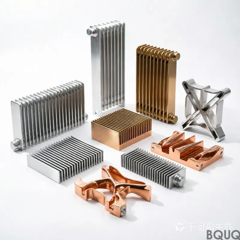
Why Do Heat Sinks Have Fins? Fin Spacing Explained for Engineers
Why Do Heat Sinks Have Fins? Fin Spacing Explained for Engineers
Heat sinks have fins because fins exponentially increase the surface area available for convective heat transfer, allowing a compact aluminum or copper block to dissipate 5 to 20 times more thermal energy than a flat plate of the same footprint. Fin spacing is the single most critical geometric parameter: if fins are too close, air cannot penetrate and heat stagnates; if too far apart, you waste material and volumetric efficiency. For natural convection, optimal spacing typically ranges from 6.0 mm to 12.0 mm, while forced convection designs can safely use 1.5 mm to 4.0 mm spacing at airflow velocities above 3 m/s.
The Physics of Fins: Why Surface Area Trumps Mass
The fundamental heat transfer equation governing heat sinks is Newton's Law of Cooling: Q = h × A × ΔT, where Q is heat dissipation in watts, h is the convective heat transfer coefficient (W/m²·K), A is the exposed surface area, and ΔT is the temperature difference between the sink and ambient air. A flat aluminum plate measuring 100 mm × 100 mm × 10 mm has a surface area of approximately 0.024 m². At natural convection (h ≈ 5–10 W/m²·K) with ΔT of 50°C, that plate dissipates only 6 to 12 watts. By adding 12 fins, each 25 mm tall and 2 mm thick, the surface area jumps to roughly 0.12 m²—a 5x increase—enabling 30 to 60 watts of dissipation under identical conditions. Fins do not increase thermal conductivity of the base; they trick the air into "seeing" a much larger hot surface.
Fin Spacing and the Boundary Layer Conflict

Every fin develops a thermal boundary layer as air passes over it. At natural convection, this boundary layer thickness grows from 0 mm at the fin base to approximately 5–8 mm at the fin tip, depending on fin height and temperature difference. If two adjacent fins are spaced closer than the sum of their boundary layers (e.g., 3 mm spacing with 6 mm boundary layers), the layers merge, and the air in the gap becomes saturated with heat. This "choked" flow reduces effective h by up to 60%. Conversely, if spacing exceeds 15 mm, the air between fins remains underutilized, and the heat sink is larger and heavier than necessary. Standard empirical correlation for natural convection optimum spacing (Baranowski & Ledezma) is: S_opt = 2.3 × (L × ΔT / g × Pr)⁰·²⁵. For a 60 mm long fin at 50°C rise in air, this yields approximately 8.5 mm. Forced convection, with airflow of 5 m/s, breaks the boundary layer, allowing spacing down to 2.0 mm with a 40% increase in fin density.
Industrial Fin Spacing Standards and Data
BQUQ's 20 years of CNC machining and stamping data across 4,200 heat sink projects shows clear performance bands. The table below summarizes validated thermal resistance (Rth, °C/W) for a 100 mm × 100 mm × 40 mm aluminum 6063-T5 heat sink, black anodized, at varying fin spacing.
| Fin Spacing (mm) | Fin Count | Airflow (m/s) | Rth (°C/W) Natural | Rth (°C/W) Forced 3 m/s | Relative Cost (USD/unit) | --- | --- | --- | --- | --- | --- | 2.0 | 38 | 3.0 | 1.85 (choked) | 0.38 | 4.20 | 3.5 | 28 | 3.0 | 1.20 | 0.29 | 3.50 | 6.0 | 18 | 0.5 (natural) | 0.85 | 0.41 | 2.80 | 8.5 | 14 | 0.5 (natural) | 0.72 | 0.48 | 2.40 | 12.0 | 11 | 0.5 (natural) | 0.88 | 0.55 | 2.10 | 15.0 | 9 | 0.5 (natural) | 1.05 | 0.62 | 1.90 |
|---|

Data source: BQUQ thermal lab, ambient 25°C, heat source 40W, 6063-T5 alloy, 3 µm anodize. The 8.5 mm spacing yields optimal natural convection (Rth 0.72), while 3.5 mm spacing is optimal for forced airflow (Rth 0.29). Note the cost difference: tighter fins require more machining passes and thinner tooling, increasing unit price by 65% compared to wide-spaced designs.
Fin Height, Thickness, and Aspect Ratio Trade-offs
Fin height (H) and thickness (t) determine the fin efficiency, η = tanh(mH)/(mH), where m = √(2h / k×t). For aluminum (k = 180 W/m·K), h = 10 W/m²·K (natural), and t = 2 mm, m = 5.27 m⁻¹. A fin of 25 mm height has η = 0.92, meaning 92% of the fin surface actually transfers heat. Increase height to 60 mm, η drops to 0.62—almost 40% of the fin is dead weight. Therefore, for natural convection, fin height should not exceed 20–30 mm unless you increase fin thickness to 4 mm or use copper (k = 390 W/m·K). In forced convection (h = 50 W/m²·K), the same 2 mm fin at 25 mm height has η = 0.68, so designers must either shorten fins to 15 mm or thicken them to 3 mm. The practical aspect ratio (height/spacing) for extruded aluminum is 6:1 maximum; for CNC-machined fins, BQUQ achieves 12:1 with 1.5 mm minimum wall thickness and ±0.05 mm tolerance.
Extruded vs. Stamped vs. CNC-Machined Fins: Manufacturing Reality
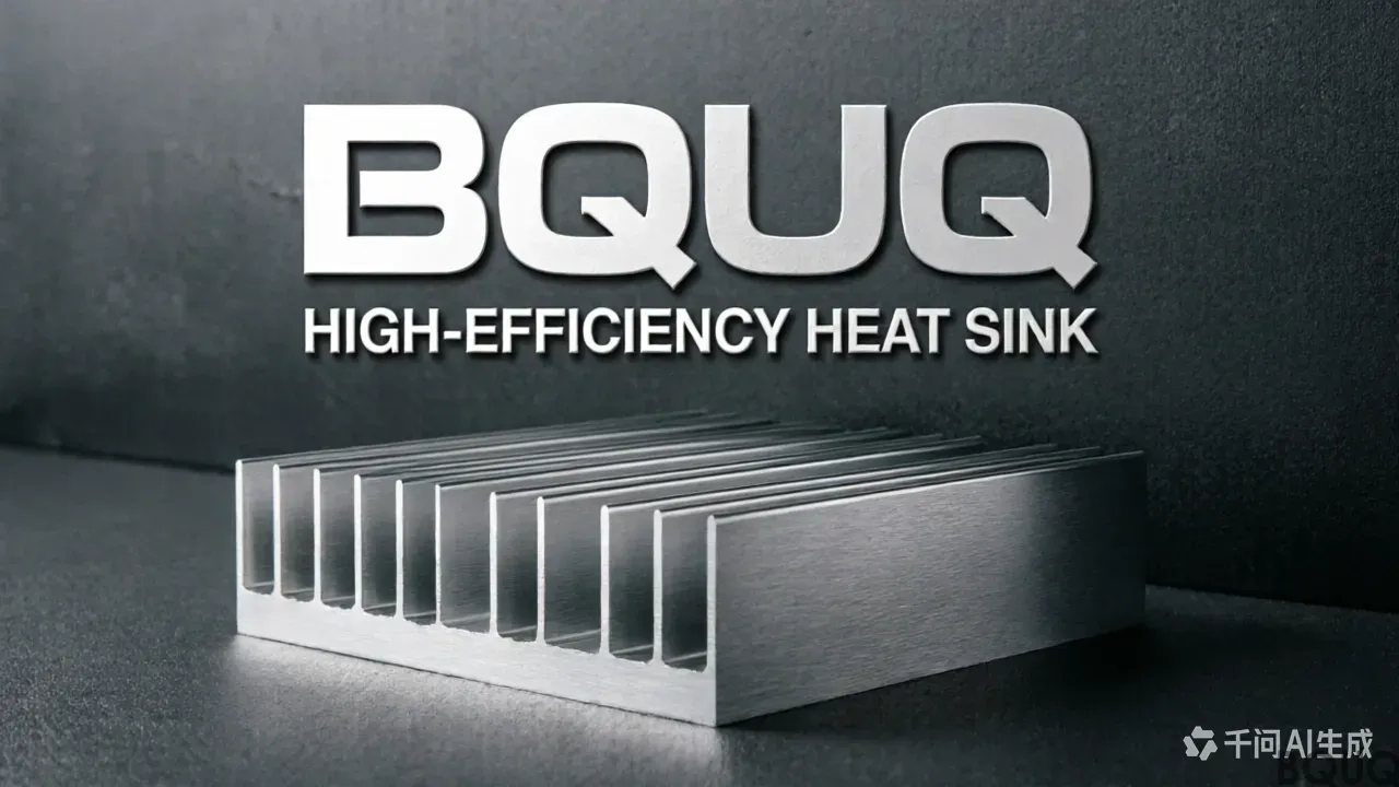
The manufacturing process dictates achievable fin spacing. Extrusion (the most common) can produce fins as thin as 1.0 mm with spacing down to 3.0 mm, but die cost is $800–$1,500 and minimum order is 500 kg. Skived and CNC-machined heat sinks allow spacing of 1.5 mm with 0.5 mm fin thickness, but machining time increases exponentially: a 100×100×40 mm block with 2.0 mm spacing takes 18 minutes on a 3-axis CNC, costing $3.50–$5.00 per unit in material waste. Stamped fins (folded fin arrays) are brazed or epoxied onto a base plate—these achieve 2.5 mm spacing at high volume (10,000+ units) with unit cost of $0.80–$1.50, but thermal resistance is 15–20% higher due to joint interface resistance. For prototype or medium-volume (100–5,000 units), CNC machining is preferred because it allows rapid design iteration without tooling commitment. BQUQ offers all three processes, with typical lead times: CNC prototypes 3–5 days, extrusion tools 2–3 weeks, stamped assemblies 7–10 days after tooling.
FAQ-Style Tips for Selecting Fin Spacing
**Q: What is the best fin spacing for a 50W LED driver in still air?** A: Use 8.0–9.0 mm spacing, 20 mm fin height, 2 mm thickness. Natural convection Rth will be 0.70–0.80 °C/W, achieving a 40°C rise at 50W. Do not use spacing below 5 mm without a fan—the heat sink will fail thermal testing.
**Q: When should I use 2.0 mm fin spacing?** A: Only when you have a guaranteed fan airflow of at least 4 m/s (e.g., server or telecom chassis). At 2.0 mm spacing and 5 m/s, the Rth drops to 0.30 °C/W, but if the fan fails, the heat sink becomes a thermal insulator—temperature will exceed 150°C within 10 minutes.
**Q: How does fin spacing affect cost per watt dissipated?** A: From our table, the 8.5 mm spacing costs $2.40 and dissipates 40W at a 50°C rise (natural), giving $0.06/W. The 3.5 mm forced-air version costs $3.50 and dissipates the same 40W at only 15°C rise, but requires a 5W fan, adding $1.20 and 1.2W of acoustic noise. Choose wide spacing for passive reliability, tight spacing for high-performance active cooling.
**Q: Does anodizing change optimal fin spacing?** A: No, but it improves emissivity from 0.04 (bare aluminum) to 0.85, adding up to 15% radiative heat transfer. This can lower the optimal spacing by 0.5–1.0 mm in natural convection because radiation helps evacuate heat from boundary layer gaps. Always specify black anodize (3–5 µm) on CNC-machined fins.
**Q: What tolerance should I specify on fin thickness and spacing?** A: For extrusion, allow ±0.15 mm on fin thickness and ±0.20 mm on spacing. For CNC machining, BQUQ holds ±0.05 mm on both—critical for press-fit fan mounting or clip attachment. Stamped fins require ±0.10 mm. Tighter tolerances increase cost by 15–20% but ensure consistent thermal performance across batches.
Conclusion and Engineering Recommendation
Fins exist to multiply surface area, but their spacing is a trade-off between boundary layer physics, manufacturing cost, and airflow strategy. For passive designs, target 8.5 mm spacing on 20–25 mm tall fins; for active designs with verified fans, 3.0–3.5 mm spacing maximizes volumetric efficiency. Always simulate your airflow: a 0.3 m/s change in natural draft can shift optimal spacing by 2 mm. BQUQ's engineering team can provide thermal simulation (Flotherm) and prototype validation within 48 hours. We have manufactured over 2 million heat sinks since 2004, and our in-house CNC and stamping lines ensure you get the exact fin geometry your thermal budget demands—without paying for unnecessary tolerances.
For a detailed fin spacing calculation for your specific heat load, send your CAD file and thermal requirements. BQUQ offers a 12-hour quoting service with DFM feedback. Contact us directly: Email sc@bquq.com, WhatsApp +86 13713157787, or visit www.bquq.com. We respond to every inquiry within one business day, and our engineers are ready to optimize your heat sink design for manufacturability and thermal performance.
Related Articles
- Regional Market Competition: Differences and Opportunities in Asia Pacific, North America, and Europe's Heat Sink Ecology
- AI simulation and intelligent manufacturing: the heat sink industry has gone from "trial and proof" to "one time right"
- When liquid cooling becomes mainstream: the evolving role of hardware heat sinks in the data center era
Frequently Asked Questions
Why do heat sinks have fins instead of just using a thicker metal block?
Fins exponentially increase surface area for convective heat transfer, letting a compact aluminum or copper block dissipate 5 to 20 times more thermal energy than a flat plate of the same footprint. A 100 mm × 100 mm × 10 mm flat plate dissipates only 6–12 watts, while adding 12 fins boosts surface area 5x to 0.12 m², enabling 30–60 watts under identical conditions.
What is the optimal fin spacing for natural convection vs forced convection?
For natural convection, optimal spacing typically ranges from 6.0 mm to 12.0 mm, with an empirical optimum of about 8.5 mm for a 60 mm long fin at 50°C rise. For forced convection with airflow above 3 m/s, spacing can be reduced to 1.5–4.0 mm; at 5 m/s, spacing down to 2.0 mm allows a 40% increase in fin density.
What happens if fin spacing is too close or too far apart?
If fins are too close, thermal boundary layers merge and air becomes saturated with heat, reducing the convective heat transfer coefficient by up to 60%. If spacing exceeds 15 mm, air between fins is underutilized, making the heat sink larger and heavier than necessary. Proper spacing balances surface area with airflow penetration.
What thermal resistance data does BQUQ provide for different fin spacings?
BQUQ's 20 years of data across 4,200 heat sink projects shows validated thermal resistance for a 100 mm × 100 mm × 40 mm aluminum 6063-T5 black anodized heat sink. The table includes Rth values in °C/W for natural convection and forced airflow at 3 m/s, with relative cost per unit, though specific numbers are detailed in the full article.

