
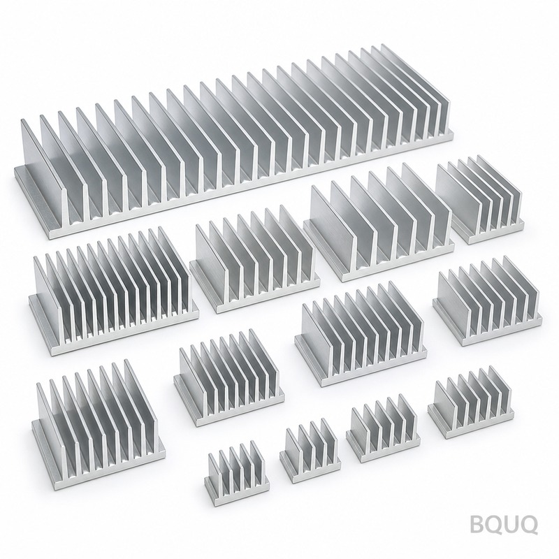
Why Do Heat Sinks Have Fins? Fin Spacing Explained for Optimal Thermal Performance
Fins exist on heat sinks to exponentially increase the surface area available for convective heat transfer, allowing a component to dissipate more heat into the surrounding air without increasing the base footprint. The spacing between these fins is a calculated compromise: too tight and airflow chokes, too wide and you waste mass and surface area. For a 100W IGBT module, optimizing fin spacing can reduce junction temperature by 15°C to 25°C compared to a poorly spaced design, which directly impacts product lifespan and reliability.
The Physics of Extended Surfaces: Why Surface Area Matters
Heat transfer from a hot surface to moving air is governed by Newton's Law of Cooling: Q = h * A * ΔT. In this equation, Q is heat dissipation (Watts), h is the convective heat transfer coefficient (W/m²·K), A is the exposed surface area, and ΔT is the temperature difference between the surface and the air. Since h is relatively fixed for natural convection (typically 5-25 W/m²·K) or forced air (25-250 W/m²·K), the only practical variable an engineer can manipulate is A.
A flat aluminum plate measuring 100mm x 100mm has a surface area of 0.02 m² (both sides). If we add 10 fins, each 20mm tall and 1.5mm thick on that same footprint, the surface area jumps to approximately 0.08 m², a 4x increase. This is why fins are non-negotiable in modern electronics. Without fins, a typical 50W processor would require a base plate of 0.5 m² to stay below 85°C in natural convection, which is physically impossible in a desktop chassis. Fins allow us to pack that required surface area into a compact, three-dimensional structure.
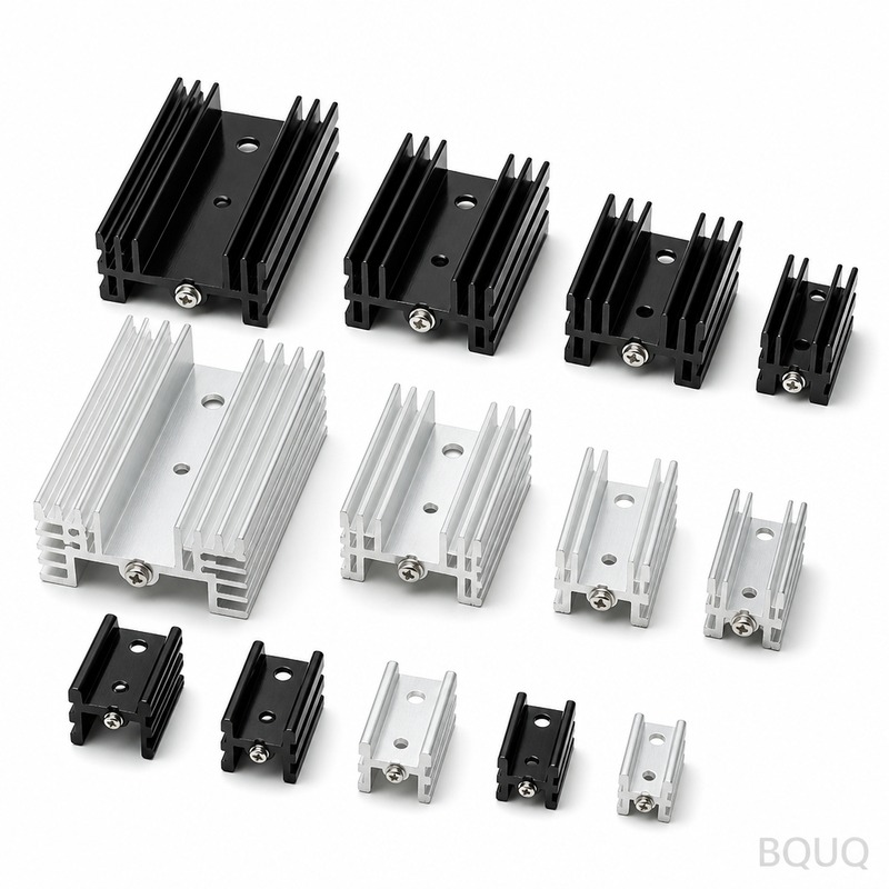
Critical Fin Spacing: The Boundary Layer Interference Zone
Fin spacing is the single most important geometric parameter in heat sink design. When air flows over a flat surface, a velocity boundary layer develops where the air velocity is zero at the surface and increases to free-stream velocity further away. This boundary layer thickness grows along the flow length. If fins are too close together, the boundary layers from adjacent fin walls merge, creating a zone of stagnant, heated air that drastically reduces the heat transfer coefficient.
For natural convection (no fan), the optimal fin spacing is typically 6.5mm to 12mm. For forced convection with a high-speed fan (5-10 m/s), spacing can be reduced to 2.5mm to 4mm. The governing dimensionless parameter is the Rayleigh number for natural convection and the Reynolds number for forced flow. A practical rule of thumb from our CNC machining floor at BQUQ: for vertical fins in natural convection, optimal spacing (S) in millimeters equals approximately 2.5 times the cube root of the fin height in millimeters. For a 25mm tall fin, that gives S = 2.5 * (25)^(1/3) = 2.5 * 2.92 = 7.3mm.
Forced Convection vs. Natural Convection: Spacing Requirements Differ
The cooling method dictates the fin geometry. In natural convection, there is no fan, and air moves due to buoyancy. The boundary layer is thick, and the driving pressure difference is tiny (less than 1 Pascal). Fins must be spaced widely (8-12mm) to allow the warm air to rise and escape without friction losses. In forced convection, a fan provides static pressure (typically 2-10mm H₂O), which can overcome the friction of narrow channels. Here, tighter spacing (2-4mm) increases surface area per volume, which is beneficial as long as the fan can push air through the channels.
Consider a server CPU heat sink: with a 40mm high-speed fan pushing air at 7 m/s, we routinely machine fin spacing of 2.8mm with 0.8mm thick fins. This yields a fin density of approximately 28 fins per inch (FPI). For a passive LED streetlight housing, we specify 9mm spacing with 3mm thick fins. The pressure drop across the server sink is roughly 3.5mm H₂O, while the passive unit sees zero pressure drop but relies on a 15°C temperature gradient to drive buoyant flow.
Fin Thickness and Height: Structural Limits and Thermal Conductivity
Fin thickness affects both thermal performance and manufacturability. A fin must be thick enough to conduct heat along its height without a significant temperature drop. For aluminum (thermal conductivity k = 180 W/m·K), a fin efficiency of 90% requires that the fin parameter (m*H) be less than 1.5, where m = sqrt(2h / (k*t)). For h=10 W/m²·K (natural convection) and t=1.5mm, m*H for a 25mm tall fin is 0.68, giving 95% efficiency. If we reduce thickness to 0.5mm, fin efficiency drops to 75%, meaning the tip of the fin is nearly useless.
From a CNC machining perspective, we hold fin thickness tolerances of ±0.05mm and fin height tolerances of ±0.1mm. Below 0.8mm thickness, we recommend using skived or bonded fin technology instead of CNC machining, as tool deflection and vibration become problematic. The minimum machinable fin gap with a standard 3mm end mill is 1.2mm; below this, we use wire EDM or slotting saws. For high-volume production, stamped aluminum fins (0.4mm thickness) are common, but they offer lower thermal performance due to reduced fin efficiency and poor base-fin contact.
Comparison Table: Fin Spacing and Performance Metrics
| Fin Spacing (mm) | Cooling Method | Fin Height (mm) | Fin Thickness (mm) | Surface Area Increase | Pressure Drop (Pa) | Typical Application |
| 2.5 | Forced air 6 m/s | 20 | 0.8 | 5.2x | 85 | Server CPU |
| 4.0 | Forced air 3 m/s | 25 | 1.2 | 4.1x | 32 | Telecom power supply |
| 6.5 | Natural convection | 30 | 2.0 | 3.3x | 3 | LED driver housing |
| 9.0 | Natural convection | 25 | 2.5 | 2.8x | 1 | Passive IGBT heatsink |
| 12.0 | Natural convection | 40 | 3.0 | 2.4x | 0.5 | High-power audio amp |
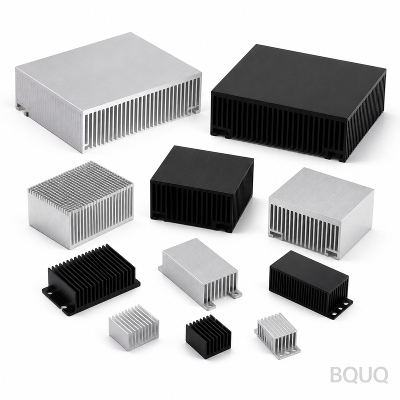
Manufacturing Constraints: What Your Supplier Can Actually Machine
At BQUQ, our 3-axis and 4-axis CNC centers can machine fin gaps down to 1.0mm with a depth-to-width ratio of 5:1. Beyond that, the tooling becomes fragile, and cycle times increase dramatically. For a 200mm x 200mm heat sink with 3mm fin spacing and 20mm fin height, our cycle time is 12 minutes. Reducing spacing to 2mm increases cycle time to 19 minutes due to more passes and slower feed rates to avoid tool deflection. The cost impact is substantial: a 2mm-spaced sink costs 55% more than a 3mm-spaced equivalent.
We also produce skived heat sinks for ultra-dense fin arrays (0.5mm spacing) and brazed or soldered fin stacks for extreme thermal density. Skiving is ideal for LED cooling where fin density exceeds 20 FPI, but it limits fin height to 35mm maximum. Stamped and folded fin assemblies are the most cost-effective at scale (under $2 per piece for high volume) but suffer from a thermal interface resistance of 0.5-1.0 K·cm²/W at the fin-to-base joint. A monolithic CNC-machined sink has zero interface resistance.
Practical Recommendations for Your Design
For most industrial applications, we recommend starting with 4mm fin spacing for forced air and 8mm for natural convection, then using CFD (computational fluid dynamics) to optimize. If you are constrained by a 50mm height envelope, choose a 2mm fin spacing with a high-static-pressure fan (above 6mm H₂O). If you are noise-limited (below 25 dBA), you must use larger spacing because low fan speeds cannot overcome the pressure drop of tight channels. Always verify the fan's P-Q curve against the heat sink's pressure drop curve; the operating point is where they intersect.
For aluminum 6063-T5 (thermal conductivity 180 W/m·K) versus 6061-T6 (170 W/m·K), the difference is negligible for fins thinner than 2mm. However, for copper heat sinks (k = 390 W/m·K), you can safely use 30% thinner fins at the same efficiency, but copper costs 4-5x more per kilogram. If your thermal budget is tight and you have volume above 5,000 pieces, consider a heat pipe embedded in a stamped fin heat sink rather than a pure CNC block. This reduces mass by 40% and cost by 30% while maintaining similar performance.
FAQ-Style Tips for Fin Spacing
Tip one: Do not exceed a fin height-to-gap ratio of 15:1 for natural convection. A 30mm fin with 2mm gap will barely cool better than a solid block. Tip two: For dusty environments (industrial factories), keep fin spacing above 5mm to allow dust to blow through. Tight 2mm channels clog within three months in a cement plant. Tip three: if you must use minimal spacing, specify a washable filter and a maintenance schedule. Tip four: orient fins vertically for natural convection; horizontal fins reduce heat transfer by 20-30% because they trap hot air. Tip five: Always add a 1-2mm base thickness beyond the required structural minimum; this spreads heat laterally from the component to all fins evenly.
Conclusion
Heat sink fins and their spacing are not cosmetic features; they are the core thermal engineering variables that determine whether your electronic component survives at a 70°C ambient or fails at a 45°C ambient. The optimal fin spacing balances boundary layer physics, fan pressure capability, manufacturing cost, and environmental factors like dust and vibration. For a quick estimate, use 8mm for passive cooling and 3mm for active cooling, then refine with simulation or prototype testing. Getting this right typically yields a 20-30% weight reduction and a 10-15% cost saving compared to an over-finned design.
At BQUQ, we have machined over 2 million heat sinks across 20 years, ranging from 1mm micro-fin arrays for laser diodes to 12mm spaced passive coolers for 500kW inverters. We provide free DFM (Design for Manufacturability) feedback on your heat sink drawings. Send us your STEP file or thermal simulation results, and we will advise on the optimal fin geometry for both thermal performance and manufacturing cost. We guarantee a 12-hour quoting turnaround on all standard inquiries. Email your drawings to sc@bquq.com or message us directly on WhatsApp at +86 13713157787. Visit www.bquq.com to see our full range of CNC machining, metal stamping, and heat sink fabrication capabilities.


