
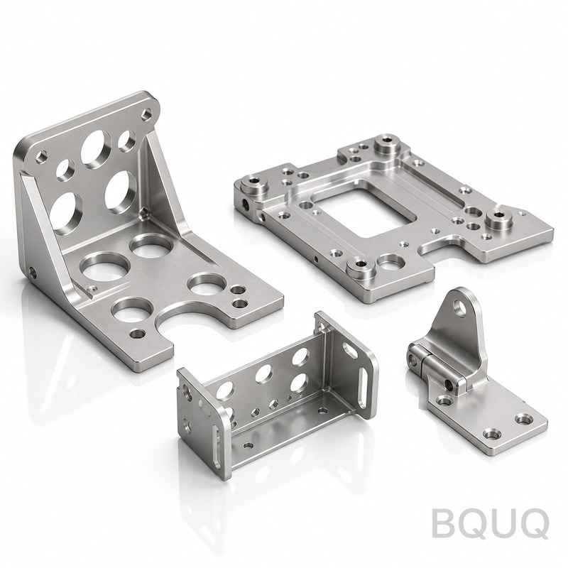
Why Do Stamped Parts Have Tooling Marks and Is That Normal for Precision Manufacturing?
Stamped parts exhibit tooling marks because the punch and die surfaces physically contact the sheet metal under high pressure, transferring microscopic irregularities and wear patterns onto the workpiece. This is a normal and expected phenomenon in all metal stamping processes, governed by ISO 2768-m standards and typically yielding surface finishes between Ra 0.8 and Ra 3.2 micrometers. Tooling marks become a quality concern only when they exceed specified tolerances or indicate premature die wear, not when they fall within the predictable range of the stamping process.
The Physical Mechanism Behind Tooling Marks
Tooling marks originate from the fundamental mechanics of sheet metal forming. During a stamping stroke, the punch exerts forces of 50 to 300 tons per square inch, depending on material thickness and hardness. This pressure causes the metal to flow into the die cavity, and any surface imperfection on the die—whether from EDM machining, wire cutting, or polishing—transfers directly to the part.
The marks fall into three categories: burnish marks (smooth, shiny areas from sliding contact), breakout marks (rough edges where the metal fractures), and die wear marks (increasingly visible as the tool undergoes 10,000 to 500,000 cycles). For a typical 1.5mm thick SPCC steel part, the burnish zone should account for 60-70% of the sheared edge, with the breakout zone comprising the remainder. This ratio is a key quality indicator.
Temperature also plays a role. At high stamping speeds exceeding 200 strokes per minute, friction raises the die surface temperature to 80-120 degrees Celsius. This thermal cycling causes micro-expansion and contraction, leaving subtle heat marks that are most visible on aluminum and copper alloys.
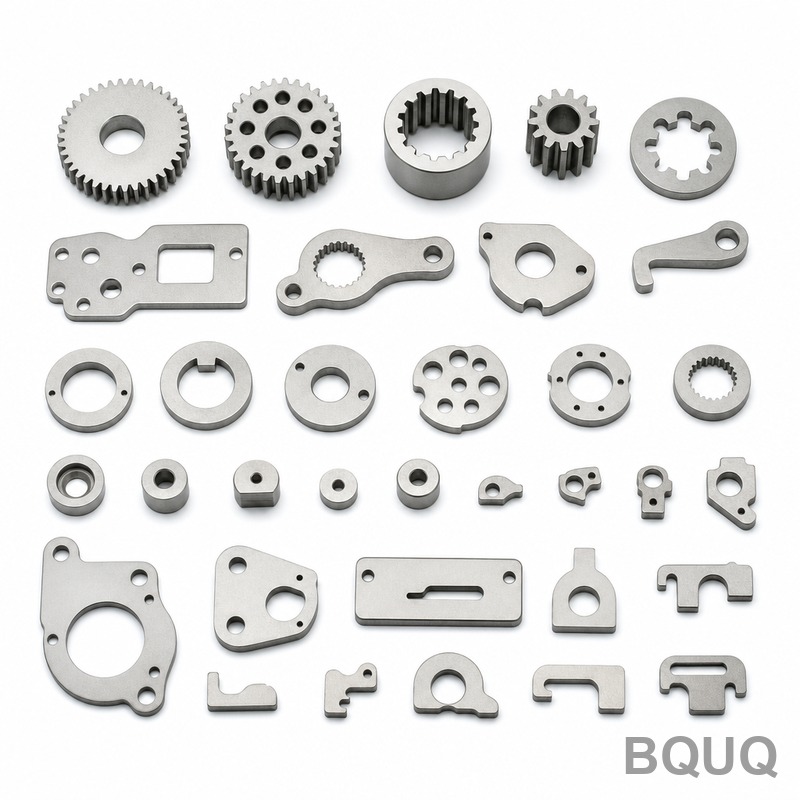
Normal vs. Defective Tooling Marks: A Comparison
| Mark Type | Appearance | Typical Location | Acceptable Limit | Cause | Inspection Method |
| Burnish lines | Smooth, parallel streaks | Sheared edges | 60-70% of edge length | Normal sliding friction | Visual under 5x magnification |
| Breakout roughness | Dull, granular texture | Bottom 30-40% of cut edge | Consistent height within 0.1mm | Ductile fracture | Optical comparator |
| Die roll | Rounded edge | Top of cut | 10-15% of material thickness | Elastic deformation | Profile projector |
| Light scratches | Hairline, uniform direction | Flat surfaces | Depth under 0.05mm | Fine die wear | Surface profilometer |
| Galling | Tear-like, rough patches | Deep draw areas | Not permitted | Material adhesion | Visual + tactile inspection |
| Orange peel | Pebbled texture | High-stretch zones | Not permitted | Grain deformation | 10x loupe comparison |
A part is considered defective when marks exceed these limits. For example, a scratch deeper than 0.05mm on a precision bracket violates the ISO 2768-m tolerance for surface defects. Galling, which indicates serious die lubrication failure, always requires immediate tool maintenance and part rejection.
How Material Selection Affects Tooling Mark Visibility
Different materials respond differently to stamping forces, directly influencing mark severity. Soft materials like 1100 aluminum (hardness 25 HB) deform easily, showing prominent die roll and burnish lines. Harder materials like 301 stainless steel (hardness 420 HB) produce cleaner edges but accelerate tool wear, leading to more pronounced die wear marks after 50,000 cycles.
Material thickness also matters. For 0.5mm brass, the burnish zone should be 70-80% of the sheared edge. For 3.0mm mild steel, this drops to 50-60% due to increased fracture zone. Engineers selecting materials must account for these differences when setting inspection criteria.
Tolerances and Standards Governing Tooling Marks
The industry does not treat all tooling marks as defects. Instead, standards define acceptable limits. ISO 2768-m allows surface irregularities of up to 0.1mm for parts with nominal dimensions under 30mm. For larger parts, the tolerance increases to 0.3mm. The automotive sector, governed by AIAG standards, typically requires tighter control: burnish depth within 0.08mm and no visible scratches beyond 0.02mm depth.
For critical applications like electrical contacts or heat sink bases, BQUQ specifies a maximum Ra of 1.6 micrometers on stamped surfaces. This requires polished dies with a surface finish of Ra 0.2 micrometers or better, achieved through diamond paste polishing and periodic reconditioning every 20,000 to 30,000 strokes.
Practical Recommendations for Engineers
First, define tooling mark acceptance criteria before production begins. Send your supplier a clear drawing with notes specifying acceptable burnish percentage, scratch depth limits, and inspection methods. This prevents disputes and ensures consistent quality across batches.
Second, request a run-at-rate trial of 300-500 pieces. Inspect parts at the beginning, middle, and end of this run. If tooling marks remain consistent in size and location, the die is stable. If marks worsen, the tool has a lubrication or alignment issue that needs resolution before mass production.
Third, for cosmetic parts visible in final assemblies, specify a secondary operation. Options include vibratory finishing (removing 0.01-0.02mm of surface material), sandblasting with 120-grit media, or micro-shot peening. These processes cost 0.01-0.05 USD per part but eliminate visible tooling marks entirely. For functional surfaces where aesthetics do not matter, skip secondary operations to save cost.
Fourth, account for tooling marks in tolerance stack-up analysis. A stamped edge with a 0.1mm breakout zone reduces the effective bearing surface. If your design requires a press-fit connection, the stamped hole diameter must account for this reduction by specifying a 0.05-0.1mm larger nominal dimension.
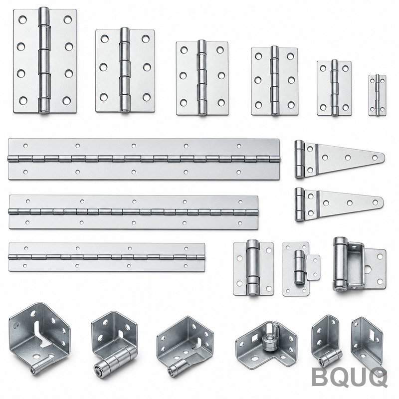
Cost and Lead Time Impact of Managing Tooling Marks
| Production Stage | Standard Die | Polished Die | Die with DLC Coating |
| Tooling cost | 1,500-5,000 USD | 2,500-8,000 USD | 3,000-10,000 USD |
| Tool lead time | 10-15 days | 15-20 days | 18-25 days |
| Maintenance interval | 50,000 strokes | 100,000 strokes | 200,000 strokes |
| Surface finish achieved | Ra 3.2 micrometers | Ra 1.6 micrometers | Ra 0.8 micrometers |
| Part price (per 1,000) | 0.10-0.30 USD | 0.12-0.35 USD | 0.15-0.40 USD |
Polished dies and DLC (diamond-like carbon) coatings reduce tooling marks but increase upfront costs by 40-60%. For high-volume production exceeding 100,000 parts, the extended maintenance interval of DLC-coated dies (200,000 strokes vs. 50,000) justifies the higher tooling cost. For low-volume prototyping under 5,000 parts, standard dies suffice because tooling marks will be minimal on a fresh tool.
FAQ-Style Tips for Common Tooling Mark Scenarios
If you see marks only on one side of the part, check the punch-to-die clearance. A clearance that is too tight (under 5% of material thickness) causes excessive burnish and heat. Too loose (over 15%) increases breakout roughness. Optimal clearance for mild steel is 10-12% of material thickness.
If marks appear only after 10,000 parts, the die is wearing normally. Request a tool inspection and re-polish schedule from your supplier. Proactive maintenance every 20,000 strokes prevents visible degradation.
If marks appear randomly across different batches, suspect material batch variation. Different steel coils from the same supplier can have hardness variations of plus or minus 10 HB, which changes the burnish-to-breakout ratio. Specify a hardness range in your material certificate requirements.
Conclusion
Tooling marks on stamped parts are a normal, quantifiable outcome of the manufacturing process, not a sign of defective workmanship. By understanding the acceptable ranges for burnish, breakout, and die wear marks, specifying clear tolerances, and choosing appropriate die finishes, engineers can balance quality and cost effectively. For precision components where surface integrity matters, partner with a manufacturer that offers both standard and polished die options and can provide documented inspection data.
At BQUQ, we maintain a 12-hour quoting service for stamped parts with clear tooling mark specifications. Send your drawings to sc@bquq.com or message us on WhatsApp at +86 13713157787 for a detailed quotation. Visit www.bquq.com to review our 20 years of CNC machining and metal stamping case studies.


