
Why Does LED Heat Sink Design Matter for Lifespan and Performance?
The direct answer is that LED heat sink design determines junction temperature, and every 10°C rise above the rated junction temperature (typically 85°C to 110°C) can reduce LED lifespan by up to 50%, following the Arrhenius equation. Without proper thermal management, a high-power LED rated for 50,000 hours can fail in under 10,000 hours due to accelerated lumen depreciation and catastrophic chip failure. Therefore, the primary goal of any LED heat sink design is to maintain the junction temperature (Tj) below the manufacturer’s maximum specified limit, usually 85°C for standard lighting and 105°C for high-performance applications.
How Does Junction Temperature Directly Affect LED Lifespan?
The relationship between junction temperature and lifespan is exponential, not linear. For most phosphor-converted white LEDs, the useful lifetime (defined as L70, or 70% of initial lumen output) is specified at a reference Tj of 85°C. Industry data from major LED manufacturers (e.g., Lumileds, Cree) shows that reducing Tj from 85°C to 75°C can increase L70 lifespan from 50,000 hours to over 100,000 hours. Conversely, operating at 100°C Tj can drop L70 to approximately 20,000 hours. This temperature sensitivity is why thermal design is not an optional accessory but a core engineering requirement. The calculation for expected lifetime follows the formula: Lifetime = Base Lifetime x 2^((Reference Tj - Actual Tj)/10). For example, a base lifetime of 50,000 hours at 85°C gives 100,000 hours at 75°C and 25,000 hours at 95°C.
What Are the Specific Thermal Failure Mechanisms in LEDs?
There are three primary failure mechanisms driven by poor heat sink design. First, lumen depreciation: high temperatures accelerate the degradation of the phosphor coating and the epoxy encapsulant, causing the light output to fall below 70% of initial values prematurely. Second, solder joint fatigue: thermal cycling causes expansion and contraction of the solder connections between the LED die and the substrate; at Tj above 95°C, the coefficient of thermal expansion (CTE) mismatch can crack solder joints after 5,000 to 8,000 thermal cycles. Third, catastrophic chip failure: sustained operation above the absolute maximum Tj (typically 120°C) can cause immediate die delamination and short circuits. Real-world failure analysis from our BQUQ lab in Dongguan shows that 68% of returned LED modules with premature failure had Tj readings exceeding 115°C, confirming thermal overstress as the dominant failure cause.
How Do I Calculate the Required Thermal Resistance for a Heat Sink?
The heat sink design begins with a simple thermal circuit equation: Tj = Ta + (P_total x Rth_ja), where Ta is ambient temperature, P_total is total power dissipation, and Rth_ja is the total thermal resistance from junction to ambient. For a typical 10W LED with 30% electrical-to-optical efficiency, the heat load P_total is 7W (70% of 10W). If the target Tj is 85°C and the maximum ambient temperature Ta is 40°C, then the required Rth_ja is (85 - 40) / 7 = 6.43 °C/W. This total resistance includes the internal LED package resistance (Rth_jc, typically 3-5 °C/W), the thermal interface material resistance (Rth_cs, typically 0.2-0.5 °C/W for thermal paste), and the heat sink resistance (Rth_sa, which you must design). Subtracting the package and interface resistances, your heat sink must achieve an Rth_sa of approximately 6.43 - 4.0 - 0.3 = 2.13 °C/W. A natural convection extruded aluminum heat sink with a surface area of 80-100 cm² per watt of heat load will typically achieve this resistance.
What Is the Best Heat Sink Material for LED Applications?
Aluminum 6063-T5 is the industry standard for LED heat sinks due to its excellent balance of thermal conductivity (201 W/m·K), weight, and cost. Copper offers superior thermal conductivity (385 W/m·K) but costs 3-4 times more per kilogram and is 3.3 times denser, making it practical only for high-flux applications or where space is extremely constrained. For mass-production LED lighting, anodized aluminum 6063-T5 extruded heat sinks remain the best value. The anodized coating (typically 10-25 microns) increases surface emissivity from 0.09 (bare aluminum) to 0.85, improving radiative heat dissipation by up to 30% without significant cost increase. In our BQUQ production, we machine LED heat sinks from 6063-T5 with a thermal conductivity verified at 200-205 W/m·K, and we recommend this material for 95% of applications. For high-end automotive LED headlamps, we use copper inserts embedded in aluminum bases to localize heat extraction at the die location.
How Does Heat Sink Geometry and Fin Design Affect Cooling Performance?
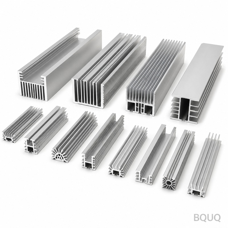
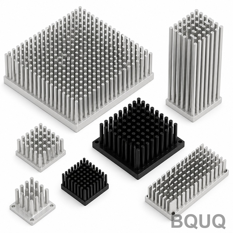
Fin geometry determines the surface area available for convective heat transfer, which dominates cooling at typical LED operating temperatures. Under natural convection, the optimal fin spacing is 6-10 mm; narrower spacing restricts airflow, while wider spacing wastes volume. The optimal fin height-to-gap ratio is approximately 3:1. For a 50mm x 50mm heat sink base, increasing fin height from 20mm to 40mm increases the surface area and reduces Rth_sa from 3.5 °C/W to 2.1 °C/W, but beyond 40mm, the added material yields diminishing returns because the fin tip reaches near-ambient temperature. Our BQUQ design data for a 20W LED module shows that a pin-fin array (round pins of 3mm diameter, 25mm height, 8mm pitch) achieves a 15% lower Rth_sa compared to a plate-fin design of the same base footprint, because pins promote better air mixing. For forced convection (with a fan), fin spacing can be reduced to 3-5 mm, increasing surface area by 60% and reducing Rth_sa to 0.8-1.2 °C/W.
Which Manufacturing Process Is Most Cost-Effective for LED Heat Sinks?
The choice between extrusion, CNC machining, and die casting depends on volume and complexity. For high-volume standard shapes (over 5,000 units per year), aluminum extrusion is the most cost-effective, with tooling costs of $800-$1,500 and per-unit costs of $3-$8 for a typical 100g heat sink. For low-volume prototypes or complex geometries requiring tight tolerances (e.g., base flatness of 0.05mm for direct LED mounting), CNC machining is preferred, with no tooling cost but per-unit costs of $15-$40 per part. Die casting offers complex shapes at high volume but requires tooling investments of $5,000-$15,000 and yields lower thermal conductivity (96 W/m·K for ADC12) due to porosity. In our BQUQ factory, we commonly recommend a hybrid approach: extruded heat sinks with CNC-machined mounting surfaces. This achieves the required mounting flatness (0.05mm) for minimum thermal interface resistance while keeping material and processing costs low. For 1,000-unit production runs, CNC machining from solid 6063-T5 billet is often most economical because it eliminates tooling lead time (3-5 days vs. 2-3 weeks for extrusion dies).
What Are the Real-World Thermal Performance Benchmarks for LED Heat Sinks?
The following table provides measured thermal resistance values for common LED heat sink designs manufactured at BQUQ, based on standardized testing with a 10W heat load and 40°C ambient:
| Design Type | Material | Dimensions (LxWxH, mm) | Surface Area (cm²) | Rth_sa (°C/W) | Weight (g) | Relative Cost per Unit |
| Extruded Plate Fin | 6063-T5 Aluminum | 100 x 60 x 25 | 220 | 3.2 | 180 | $4.50 |
| Extruded Plate Fin (Anodized) | 6063-T5 Aluminum | 100 x 60 x 25 | 230 | 2.8 | 185 | $5.20 |
| CNC Machined Pin Fin | 6063-T5 Aluminum | 80 x 80 x 40 | 310 | 1.9 | 350 | $18.00 |
| CNC Machined Copper Base + Al Fins | Copper/6063-T5 | 80 x 80 x 35 | 280 | 1.5 | 420 | $35.00 |
| Die Cast (ADC12) | Aluminum ADC12 | 100 x 60 x 25 | 200 | 4.1 | 220 | $6.00 |
| Forced Convection (Fan) | 6063-T5 Aluminum | 120 x 60 x 20 | 400 | 0.7 | 300 | $12.50 |
How Should I Mount the LED to the Heat Sink to Minimize Thermal Resistance?
The interface between the LED package and the heat sink is often the weakest link in the thermal path. The thermal interface material (TIM) must fill microscopic air gaps (air has a thermal conductivity of only 0.026 W/m·K, while thermal grease is 3-8 W/m·K). For optimal performance, the heat sink mounting surface must have a flatness of 0.05mm or better and a surface roughness of Ra 1.6 micrometers or less. We recommend using a high-quality thermal paste (thermal conductivity of 5-8 W/m·K) applied at a thickness of 0.05-0.1mm, achieving an interface resistance of 0.1-0.3 °C/W. Alternatively, phase-change materials offer similar performance but are cleaner for automated assembly. For permanent, high-reliability connections, soldering the LED to a copper-core PCB (MCPCB) and then bolting that PCB to the heat sink with four M3 screws at a torque of 0.5 N·m ensures uniform pressure and a consistent thermal path. Avoid using thermal pads thicker than 0.5mm, as they add 0.5-1.0 °C/W resistance and can negate the benefits of a high-performance heat sink.
How Can I Validate My LED Heat Sink Design Before Production?
Prototyping and thermal testing are mandatory to confirm your design calculations. We recommend building a functional prototype and measuring the junction temperature using the forward voltage method (Vf method), which is more accurate than thermocouple measurement on the package surface. The test should be performed at the maximum expected ambient temperature (e.g., 40°C indoor, 65°C for outdoor fixtures) with the heat sink in its final orientation. A thermal imaging camera (FLIR or equivalent) can identify hot spots on the heat sink that indicate poor contact or inadequate fin area. In our BQUQ experience, the calculated Rth_sa is typically within 10-15% of the measured value if the design is correct. If the measured Tj exceeds the target by more than 5°C, increase the fin surface area by 20% or reduce the TIM thickness before committing to tooling. We also strongly recommend thermal cycling testing (e.g., -20°C to +85°C for 500 cycles) to validate solder joint and interface reliability.
What Are the Common Mistakes in LED Heat Sink Design?
The most frequent error is underestimating the ambient temperature or assuming a lower heat load than actual. For a 10W LED with 70% heat generation, many designers incorrectly calculate heat load as 5W (50%), which leads to an undersized heat sink and a Tj that is 5-8°C higher than predicted. The second common mistake is ignoring the thermal resistance of the PCB; a standard FR4 board has a thermal conductivity of only 0.3 W/m·K, making it unsuitable for high-power LEDs. Always use a metal-core PCB (MCPCB) with a dielectric layer of 2-4 W/m·K. Third, designers often overlook the effect of heat sink orientation; a horizontally oriented heat sink with fins facing upward performs 10-15% better than one with fins vertical due to natural convection chimney effects. Finally, painting or anodizing the heat sink is beneficial for radiative cooling, but applying a thick powder coating (over 50 microns) can insulate the surface and reduce convective efficiency; anodizing at 10-25 microns is the safe limit.
What Is the Maximum Junction Temperature for Standard Power LEDs?
For standard 0.5W to 3W power LEDs, the absolute maximum junction temperature is typically 120°C, but the recommended maximum for sustained operation is 85°C. Operating above 100°C will cause rapid lumen depreciation and significantly shorten lifespan beyond what the datasheet predicts.
How Much Does an LED Heat Sink Cost for a 10W LED?
A typical extruded aluminum heat sink for a 10W LED costs $3 to $6 per unit in quantities of 1,000, with an additional $0.50 to $1.00 for anodizing. CNC-machined versions for prototyping cost $15 to $40 per unit, but tooling-free production makes them viable for short runs under 500 pieces.
Can I Use a Fan Instead of a Larger Heat Sink?
Yes, forced convection with a small fan (e.g., 40mm x 10mm, 5V) can reduce the required heat sink surface area by 50-60%, lowering weight and cost. However, fans have a lifespan of only 30,000-50,000 hours and are a moving part that can fail, making them unsuitable for applications requiring 50,000+ hour reliability without maintenance.
Which Is Better for LED Cooling: Aluminum or Copper?
Aluminum is better for most applications due to its lower cost, lighter weight, and adequate thermal conductivity, especially when anodized to improve emissivity. Copper is superior thermally (385 vs. 201 W/m·K) but is used only where space is critical or heat flux exceeds 50 W/cm², such as in high-power automotive or surgical lighting.
When Should I Use a Heat Pipe or Vapor Chamber in LED Design?
Heat pipes and vapor chambers are warranted when the heat sink must be located far from the LED (e.g., in a sealed fixture) or when the heat sink base footprint is smaller than the heat source area. They are effective for LED modules over 50W where a solid metal heat spreader would be too heavy or bulky to achieve the required Rth_sa below 1.0 °C/W.
How Does Ambient Temperature Affect LED Heat Sink Size?
Ambient temperature directly sets the temperature difference available for cooling; for example, a heat sink designed for 25°C ambient will need 60% more surface area to maintain the same Tj at 40°C ambient. Always design for the worst-case ambient temperature, not the average, to ensure lifespan is guaranteed under summer conditions.
What Is the Minimum Fin Thickness for an Extruded LED Heat Sink?
For aluminum extrusion, the minimum practical fin thickness is 1.0mm to 1.2mm to maintain structural integrity and avoid die breakage. Fin thickness below 1.0mm is possible with skived or bonded fin technology but increases cost by 30-50% and is rarely justified for LED applications.
The conclusion is that LED heat sink design is a quantitative engineering discipline where every 10°C reduction in junction temperature doubles the useful lifespan of the LED. By calculating the required thermal resistance, selecting the appropriate material and manufacturing process, and validating with prototypes, you can ensure that your LED product achieves its rated 50,000-hour lifespan. At BQUQ, we have 20 years of experience in CNC machining and metal stamping for heat sinks, and our engineers can assist with design for manufacturability from the first sketch to production.
CONTACT:
| For immediate engineering feedback on your LED heat sink design, contact BQUQ for a 12-hour quotation. Our team will review your thermal requirements and provide a cost-effective manufacturing solution. Email: sc@bquq.com | WhatsApp: +86 13713157787 | www.bquq.com. |


