
BQUQ compares server cooling paths: air heat sinks, cold plates and AI loads, with Rth numbers, rack power limits and machining facts from Dongguan.
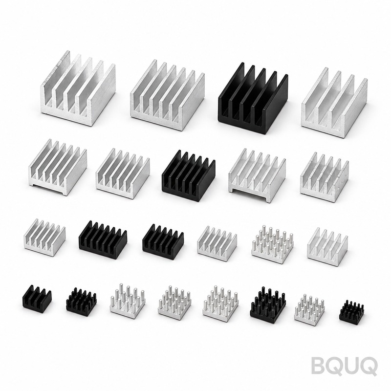
Heat Sinks for Servers: Air, Cold Plate and the AI Load
Short answer: air cooling with heat pipe or vapor chamber heat sinks still handles mainstream CPUs up to roughly 300–400 W in 1U/2U servers, but AI accelerators at 700 W and above have pushed the industry to liquid cold plates that hold chip-to-coolant resistance near 0.02–0.06 K/W. The crossover is economic as much as physical: above about 20–30 kW of heat per rack, air cooling needs so much airflow and power that liquid wins on total cost. If your part is a machined copper or aluminum cold plate, tolerances on the coolant channel and mounting face are what make or break the thermal number.
Server thermal design used to be a catalog exercise: pick the biggest heat sink that fits the socket keep-out and check the fan speed. That era ended when CPU power climbed past what a solid aluminum fin block could reject, and it ended again when GPU and AI accelerator modules tripled the power density in a single generation. Understanding where air stops and liquid starts is now a buying decision, not a physics footnote.
The Air Path: Heat Pipes and Vapor Chambers
Almost every air-cooled server heat sink today is a copper or aluminum base with heat pipes or a vapor chamber spreading heat into a dense aluminum fin stack. The heat pipes move heat laterally at effective conductivities far above solid metal, then the fin stack dumps it into ducted fan airflow. Typical performance for a high-end 1U heat sink: 0.15–0.30 K/W case-to-air at 10–20 CFM of forced air, enough for a 200–300 W CPU at reasonable junction temperatures.
The physics limit is not exotic. A 300 W chip needs the sink-to-air resistance around 0.25 K/W to hold a 75 °C rise, which means moving roughly 300 W through fins with air that has a specific heat of only about 1 kJ/kg·K. Doubling the chip power forces either doubling the airflow, doubling the surface, or both, and at rack scale that math collides with fan power and noise. The result: air-cooled racks are practical up to roughly 15–30 kW of IT heat load depending on density, and beyond that the airflow required becomes absurd.
| Cooling path | Typical Rth chip-to-fluid | Practical power per socket | Rack heat capacity |
|---|---|---|---|
| Air, 1U heat pipe sink | 0.15–0.35 K/W | 150–350 W | 15–30 kW |
| Air, 2U tall sink | 0.10–0.25 K/W | 250–450 W | 20–35 kW |
| Cold plate, rack liquid | 0.03–0.08 K/W | 350–1000+ W | 50–150+ kW |
| Direct-to-chip with immersion | — | Any | 100 kW+ density |
Those rack numbers are indicative ranges for conventional air distribution and typical 19-inch racks; high-density AI racks now exceed 100 kW and only liquid paths keep them below thermal limits. The crossover point is around 20–30 kW per rack, which is why hyperscale AI deployments spec liquid cooling as standard.
Cold Plates: Machining Is the Thermal Design
A cold plate is a metal block with internal coolant channels, mounted directly on the chip. Its job is to get heat into moving water with the smallest possible temperature drop, and because water's convection coefficients run 100–1,000 times higher than air, the resistance that matters is no longer the fluid side but the metal and the interface. A well-made copper cold plate holds chip-to-coolant resistance near 0.02–0.06 K/W at 1–2 L/min flow.
What makes one cold plate beat another is manufacturing. Channel geometry sets both thermal performance and pressure drop: more and narrower channels improve heat transfer but raise pumping pressure, and the classic design problem is balancing Rth against a pressure-drop budget of typically 10–50 kPa at the rack manifold. The mounting face must be flat to a few hundredths of a millimeter so the TIM layer stays thin, and the channels must be machined or formed without burrs that shed into the coolant loop. This is precision CNC territory, and it is why machined cold plates are usually CNC-milled from copper C110 or aluminum, then nickel-plated or left bare depending on coolant chemistry.
| Cold plate material | Conductivity | Typical use | Machining note |
|---|---|---|---|
| Copper C110 | ~390 W/m·K | AI accelerators, high flux | CNC milled, more expensive |
| Aluminum 6061 | ~170 W/m·K | General CPUs, lighter loops | Cheaper, needs corrosion care |
| Copper with nickel plating | ~390 W/m·K | Mixed-metal coolant loops | Plating thickness must be controlled |
| Hybrid copper base + aluminum body | — | Cost-down designs | Joint quality decides performance |
Material choice is a system decision, not a component decision. Aluminum is fine in an all-aluminum loop with inhibited coolant, but mixing copper cold plates with aluminum radiators invites galvanic corrosion unless the coolant chemistry or plating handles it. Copper costs more and machines slower but buys roughly 2× conduction, which at AI power densities is real headroom. For a deeper comparison of conductor trade-offs see our aluminum vs copper analysis.
The AI Load: What Changed
AI accelerators changed the thermal target in three ways. Power per chip climbed from the 300–400 W CPU class to 700 W and beyond, and the die area did not grow at the same rate, so heat flux at the chip surface roughly doubled. Second, the systems pack eight or more accelerators per node, so the thermal problem moved from one hot spot to an entire rack full of them. Third, utilization is continuous: AI training runs chips at full load for days, not the bursty pattern of general servers, so peak thermal design is the steady state.
The result is that cold plates for AI are no longer optional engineering exercises. A typical AI server cold plate must move 700–1,200 W per accelerator with the coolant entering around 25–45 °C and leaving 10–15 °C hotter, and the plate's spreading resistance under a multi-die module matters as much as its channel performance. Manufacturers machine these plates with tight channel tolerances, pressure-test every unit, and qualify the mounting surface flatness, because a warped plate or a leaking joint turns a thermal design into a data-center flood. This is also why the heat pipe vs heat sink decision still matters for the air-cooled remainder of the fleet even as flagships go liquid.
Specifying a Server Heat Sink or Cold Plate
When you send a server thermal part to a factory, the specifications that matter are the ones that affect the thermal path. For air heat sinks: base material, heat pipe count and layout, fin density, and the load that must be held at the socket. For cold plates: coolant, flow rate and inlet temperature, pressure-drop budget, chip footprint and hot-spot map, and the mounting and sealing requirements. State the failure criterion too: is the number a maximum case temperature at a stated ambient, or a full thermal resistance budget?
Machined base flatness is the specification buyers most often forget. A heat sink base that is flat to 0.05 mm with a good TIM behaves completely differently from one that rocks on the chip with an air gap under half the die. At BQUQ we hold ±0.005 mm on critical machined features, machine the thermal face and the mounting holes in the same setup where possible, and pressure-test liquid parts before shipping. Send the thermal target, not just the drawing, and we will flag the features that decide whether you meet it.
Lead Times, Tooling and Volume for Server Thermal Parts
The volume story for server thermal parts runs opposite to intuition. Cold plates and sink bases are low-volume, high-precision components, so CNC machining is the default: there is no die to pay for, geometry changes cost only programming time, and a prototype is machined with the same process as the production part. That makes machined parts ideal for the qualification cycle of a new server platform, where the thermal solution changes with every CPU generation and tooling would be obsolete before it amortized.
At higher volume, the design splits into parts that suit different processes. A copper cold plate stays machined because the channel geometry and flatness demands do not relax with volume. The aluminum parts around it — mounting brackets, stiffeners, stamped fin packs for air-cooled sections — can move to extrusion or stamping once the design freezes, which is where cost per part drops by half or more against machining. The engineering trick is designing the split early, so the machined thermal core and the stamped structural parts are specified to their own processes instead of fighting them.
Qualification steps deserve schedule space. Pressure testing of cold plates is typically 100% at volume, with leak rates specified by the system integrator; flatness of the chip-facing surface is checked on every part that carries a TIM; and plating thickness on nickel-plated copper is sampled against the coolant chemistry spec. Each of these is a routine operation in a precision plant, but each needs a defined spec, and defining them late is how thermal programs slip. Send the target Rth, coolant type, flow rate and pressure-drop budget with the drawing, and the quote should return with the process split and the inspection plan attached.
At BQUQ we machine copper and aluminum cold plates and sink bases at ±0.005 mm, finish the thermal faces in the same setup as the mounting holes, and coordinate plating and pressure testing through qualified partner processes. Because we also run stamping and spring lines, the structural parts of the same assembly can be quoted in the same email. Send the assembly drawing to sc@bquq.com or WhatsApp +86 13713157787, and the 12-hour quote will separate the machined core from the parts that should be stamped or extruded.
Frequently Asked Questions
Q: When should a server switch from air to liquid cooling?
A: As a rule of thumb, when rack heat load exceeds roughly 20–30 kW or chip power exceeds about 400–500 W per socket, liquid cooling starts winning on total cost and reliability. Below that, air heat sinks with heat pipes or vapor chambers are cheaper and easier to service.
Q: What is a typical cold plate thermal resistance?
A: A well-designed copper cold plate runs about 0.02–0.06 K/W chip-to-coolant at 1–2 L/min, with pressure drop in the 10–50 kPa range. The exact number depends on chip footprint, channel design, coolant temperature and flow.
Q: Why are AI server heat sinks so much bigger than CPU coolers?
A: Because AI accelerators dissipate 700 W and above continuously, roughly double a high-end CPU, and they run at full load for days. The heat sink or cold plate is sized for steady-state full load, and the heat flux per square centimeter is higher too, which demands more surface, more heat pipes, or liquid.
Q: What causes cold plate performance to fall short of design?
A: Usually manufacturing quality: channel geometry variation, a mounting face that is not flat, burrs or debris in the channels, or plating thickness variation. These are controlled by machining tolerance and 100% pressure testing, which is why precision CNC production matters for liquid parts.
Q: Can BQUQ machine server heat sinks and cold plates?
A: Yes. We CNC machine copper and aluminum sink bases, heat pipe grooves and cold plates, hold ±0.005 mm on critical features, and can add nickel plating and pressure testing through our partner processes. Send your drawing and thermal target to sc@bquq.com or WhatsApp +86 13713157787 for a quote within 12 working hours.
Related Resources
- Air Cooling vs Liquid Cooling — deciding the architecture before the component.
- Heat Pipe vs Heat Sink — how spreaders change what a fin stack can do.
- CNC-machined heat sinks — precision bases, grooves and cold plates machined in Dongguan.
- Contact us — send your drawing for a quote within 12 working hours.
Authored by the BQUQ Engineering Team. BQUQ is an ISO9001-certified source factory in Dongguan, China, running CNC machining, metal stamping, custom springs, heat sink and collet lines under one roof. Send drawings to sc@bquq.com or WhatsApp +86 13713157787 for a quote within 12 working hours. www.bquq.com


