
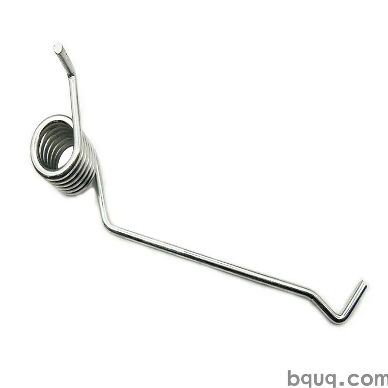
Designing Springs for Dynamic Loads and Resonance
Short answer: Design for dynamic loads by keeping the spring's natural frequency at least 15–20× the excitation frequency, capping corrected shear stress so that the fatigue limit is not exceeded, and controlling the surge wave with more active coils, larger wire, or added damping. In practice, a steel compression spring with a 25 mm mean diameter, 3 mm wire, and 8 active coils resonates near 90–130 Hz; if your machine excites it at 50 Hz, you must change geometry, not just material. BQUQ machines and winds such springs in one Dongguan ISO9001 factory, quotes in 12 working hours.
Static spring design is a two-variable problem: force and deflection. Dynamic design adds two more variables — time and frequency — and those are where most field failures begin. A spring that passes every static check can still break in a few hundred thousand cycles because it is being driven near its own natural frequency, because stress at the inside of the coil exceeds the fatigue limit, or because a surge wave is stacking coils into solid contact at speed.
This article covers the engineering workflow: natural frequency calculation, resonance avoidance, surge wave control, damping, fatigue stress limits, and the manufacturing tolerances that make dynamic performance repeatable. All figures are typical and indicative; final values depend on your specific geometry, material, and duty cycle.
Why do dynamic loads break springs that pass static checks?
A static check asks one question: does the spring deflect to the required length without exceeding allowable stress? A dynamic check asks a harder question: does the spring survive millions of cycles at that stress, at that frequency, in that environment?
Three mechanisms cause most dynamic failures:
- Fatigue cracking. Cyclic shear stress initiates a crack at the inside diameter of the coil, typically at the point of maximum curvature. Cracks propagate until the wire separates. The failure surface usually shows a smooth initiation zone and a rougher final fracture zone.
- Resonance and surge. At certain frequencies, a compression wave travels up and down the spring, causing some coils to move while others are nearly stationary. Local stresses can be several times the nominal value.
- Impact and coil clash. If the spring compresses to solid height during a dynamic event, coils collide. The resulting shock loads are far above the design stress.
A spring that passes a static check but fails at 200,000 cycles is usually a fatigue or resonance problem, not a material problem. Changing from music wire to chrome-silicon steel helps only if the stress level drops below the fatigue limit of the new material.
How do you calculate a spring's natural frequency?
For a helical compression spring with both ends fixed against rotation, the fundamental natural frequency in Hz is approximated by:
f = (1/2) × √(k / m)
where k is the spring rate in N/m and m is the active mass of the spring in kg. A more practical form used in spring design references is:
f ≈ (d / (π × D² × N_a)) × √(G / (32 × ρ))
where d is wire diameter, D is mean coil diameter, N_a is the number of active coils, G is shear modulus, and ρ is material density. For steel, G ≈ 79,300 MPa and ρ ≈ 7,850 kg/m³.
The key insight is that natural frequency scales with wire diameter and inversely with mean diameter squared and active coil count. To raise natural frequency, use thicker wire, a smaller mean diameter, or fewer active coils. To lower it, do the opposite.
Worked example: 3 mm wire, 25 mm mean diameter, 8 active coils
| Parameter | Value |
|---|---|
| Wire diameter d | 3.0 mm |
| Mean coil diameter D | 25 mm |
| Active coils N_a | 8 |
| Shear modulus G | 79,300 MPa |
| Density ρ | 7,850 kg/m³ |
| Estimated fundamental frequency | ~100–130 Hz |
This spring will resonate if the machine excites it in that band. If your application runs at 50 Hz, you have a 2–2.6× margin — too thin for safety. Aim for a natural frequency at least 15–20× the excitation frequency, or at least 0.5× if you cannot get above it and must design below the band.
Design targets for frequency margin
| Excitation frequency | Minimum natural frequency | Typical action |
|---|---|---|
| 10 Hz | 150–200 Hz | Increase wire diameter or reduce active coils |
| 25 Hz | 375–500 Hz | Redesign geometry; material change alone insufficient |
| 50 Hz | 750–1000 Hz | Often requires stiffer, shorter spring or damping |
| 100 Hz | 1500–2000 Hz | Consider a different spring type or a damper |
If the required natural frequency is impractical, the correct answer is usually to change the system — add a damper, change the cam profile, or move the spring to a location with lower excitation. Forcing a spring into a resonance-prone design is a reliability problem you will pay for in warranty claims.
What is spring surge, and how do you control it?
Surge is a compression wave traveling along the spring axis. When the excitation frequency matches the natural frequency, the wave reflects between the ends and creates standing-wave behavior. Some coils move a lot; others barely move. The local stress at the moving coils can be several times the nominal stress calculated from force and deflection.
Surge is most damaging in springs with many active coils and low natural frequency — long, soft springs. It shows up as a buzzing or ringing noise, erratic force output, and early fatigue failure at the coil that moves most.
Control methods, in order of practicality:
1. Increase natural frequency. Thicker wire, smaller mean diameter, fewer active coils. This is the most effective single change.
2. Add damping. Friction between coils, a damping sleeve, or a spring with a close-wound end that rubs. Damping reduces amplitude at resonance but does not eliminate the frequency match.
3. Use a nested or dual-rate spring. Two springs with different natural frequencies reduce the chance that both resonate at the same excitation.
4. Change the excitation. If the machine speed is adjustable, moving away from the resonance band is often cheaper than redesigning the spring.
For a deeper look at how cyclic stress accumulates in rotating applications, see spring rotational fatigue.
How do you design for fatigue life?
Fatigue design means keeping the alternating shear stress below the material's fatigue limit for the required cycle count. The governing stress is the corrected shear stress at the inside of the coil:
τ = K_w × (8 × F × D) / (π × d³)
where K_w is the Wahl correction factor, F is the applied force, D is mean coil diameter, and d is wire diameter. For dynamic design, you need both the mean stress and the alternating stress:
- τ_mean = (τ_max + τ_min) / 2
- τ_alt = (τ_max − τ_min) / 2
Then compare against a fatigue diagram (Goodman or Soderberg) for the material. Typical fatigue limits for spring steels, expressed as a fraction of ultimate tensile strength, are:
| Material | Typical fatigue limit (shear, as % of UTS) | Notes |
|---|---|---|
| Music wire | 40–45% | Good fatigue, limited corrosion resistance |
| Chrome-silicon | 45–50% | Excellent fatigue, needs protection |
| Chrome-vanadium | 45–50% | Good at elevated temperature |
| 302 stainless | 30–35% | Corrosion resistant, lower fatigue |
| 17-7 PH | 40–45% | Good corrosion plus fatigue |
These are indicative values. Surface condition, shot peening, and residual stress change them significantly. Shot peening can raise fatigue life by 20–50% in typical compression springs by putting the surface in compression. Stress relief after coiling removes residual tensile stress that would otherwise accelerate crack initiation. See spring stress relief for process details.
Presetting and shot peening
Presetting (scragging) compresses the spring to solid height once, creating beneficial residual stresses at the inside of the coil. Shot peening bombards the surface with small media, creating a compressive layer. Both are standard for dynamic springs and both add cost. For a spring that must survive 10⁶ cycles, they are usually worth it.
What role do tolerances and materials play?
Dynamic performance is sensitive to geometry. A 5% variation in wire diameter changes stress by roughly 15% (stress scales with d³). A 5% variation in mean diameter changes stress by about 5%. This is why dynamic springs need tighter tolerances than static ones.
| Parameter | Typical static tolerance | Typical dynamic tolerance |
|---|---|---|
| Wire diameter | ±0.02 mm | ±0.01 mm |
| Outside diameter | ±0.15 mm | ±0.08 mm |
| Free length | ±1.0 mm | ±0.5 mm |
| Load at test length | ±10% | ±5% |
| Squareness | 2° | 1° |
Material choice follows the fatigue and environment requirements. Music wire offers the best fatigue performance per unit cost for small springs. Chrome-silicon is the workhorse for high-cycle automotive and industrial springs. Stainless grades trade fatigue life for corrosion resistance. For high-temperature or corrosive environments, consider beryllium copper springs or 17-7 PH.
How does BQUQ manufacture dynamic-duty springs?
BQUQ runs CNC machining, metal stamping, custom springs, and heat sink production across four production lines in one Dongguan factory, under ISO9001. Spring manufacturing covers compression, extension, and torsion types, with CNC coiling, stress relief, shot peening, and preset operations available.
For dynamic applications, the process sequence matters as much as the design:
1. Wire incoming inspection — diameter, tensile strength, surface condition.
2. CNC coiling — pitch and diameter controlled to tight tolerance.
3. Stress relief — removes residual stress from coiling.
4. End grinding — squareness and flatness for compression springs.
5. Shot peening — compressive surface layer.
6. Presetting — residual stress stabilization.
7. Load testing — 100% or sample inspection at test length.
Because all four lines sit in one factory, a spring that needs a stamped retainer or a machined seat can be produced and validated together. That shortens the loop between design change and functional test. Quotes are issued in 12 working hours, and MOQ is flexible for prototype and pilot runs.
For assemblies where the spring interacts with a machined or stamped component, see spring failure analysis for how interface problems present in the field.
Frequently Asked Questions
Q: What natural frequency should I target for a spring in a dynamic application?
A: Target a natural frequency at least 15–20× the excitation frequency if you can achieve it. If that is impractical, design well below the band — under 0.5× — and add damping. A spring with a natural frequency within 20% of the excitation frequency will surge and fatigue quickly. Geometry changes are usually more effective than material changes.
Q: Can shot peening really extend spring fatigue life?
A: Yes, typically by 20–50% in compression springs, because it creates a compressive residual layer at the surface where fatigue cracks initiate. The benefit depends on intensity, coverage, and material. Shot peening does not fix a resonance problem or an overstressed design; it improves the fatigue margin once the stress level is already acceptable.
Q: How do I know if my spring is surging?
A: Symptoms include a buzzing or ringing noise at a specific machine speed, erratic force output, heat buildup, and fatigue cracks appearing at a coil away from the ends. If the failure location is not at the point of maximum nominal stress, surge is a likely cause. Instrumented force measurement at speed will show the oscillation directly.
Q: Does a stiffer spring always have a higher natural frequency?
A: Not necessarily. Natural frequency scales with the square root of rate divided by mass. A stiffer spring made from thicker wire also has more mass, so the two effects partly cancel. In practice, increasing wire diameter and reducing active coils raises frequency, but you must calculate rather than assume. Rate alone is not a reliable proxy.
Q: What tolerances matter most for dynamic springs?
A: Wire diameter and load at test length. Stress scales with the cube of wire diameter, so a 5% diameter variation changes stress by about 15%. Load tolerance controls the installed force and therefore the mean stress. For dynamic duty, specify ±0.01 mm on wire and ±5% on load, tighter than typical static tolerances.
Related Resources
- About BQUQ — ISO9001 factory profile and four production lines in Dongguan
- Compression springs — CNC-coiled, stress-relieved, shot-peened options
- Torsion springs — leg design and dynamic torque applications
- Extension springs — initial tension and hook design for cyclic loads
- Industry trends — sourcing and manufacturing shifts in precision components
- Technical articles — full engineering library on springs, stamping, and CNC
- Contact — send drawings for a quote in 12 working hours
Authored by the BQUQ Engineering Team. BQUQ (Dongguan) runs CNC machining (±0.005 mm), metal stamping, custom springs, and heat sink production in one ISO9001 factory. Source-direct from Dongguan, China — quote in 12 hours: sc@bquq.com | WhatsApp +86 13713157787 | www.bquq.com


