
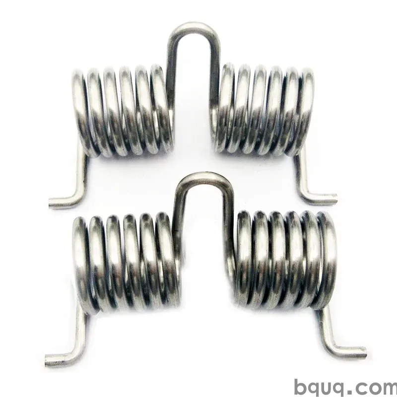
Springs for Vibration Isolation: Rate and Natural Frequency
Short answer: A spring isolates vibration only when its natural frequency is well below the excitation frequency — a ratio of 3:1 or more, meaning the spring's natural frequency should sit at or under one-third of the driving frequency. For a 25 Hz motor, target 8 Hz or lower. Natural frequency scales with the square root of spring rate divided by supported mass, so halving frequency requires cutting rate to one-quarter. In practice you choose a soft, long-travel spring with enough static load capacity, then verify deflection, stress and buckling. BQUQ machines and winds isolator springs to ±0.005 mm CNC tolerances in Dongguan, quoting in 12 working hours.
What Is Vibration Isolation, Physically?
Vibration isolation means interrupting the path by which oscillating force travels from a machine into a structure — or from a floor into a sensitive instrument. A spring does this by introducing a compliant element between the two. Instead of transmitting force rigidly, the spring stores and releases energy, and the mass it supports becomes a resonator with its own frequency.
Two regimes matter:
- Amplification region: when the driving frequency is near the spring-mass natural frequency, motion is amplified, not reduced. This is the resonance zone and it is destructive.
- Isolation region: when the driving frequency is well above the natural frequency, transmissibility drops. Force transmitted falls as the frequency ratio rises.
The transition is the design problem. Every isolator passes through resonance during startup and shutdown, so the spring must survive it, and the system must either damp through it quickly or be restrained by snubbers.
Transmissibility in One Equation
For a single-degree-of-freedom system with viscous damping ratio ζ and frequency ratio r = f_driving / f_natural:
T = √[ (1 + (2ζr)²) / ( (1 − r²)² + (2ζr)² ) ]
At r = 3 and ζ = 0.05, T ≈ 0.13 — roughly 87% of the disturbing force is blocked. At r = 5, T ≈ 0.045. This is why the 3:1 rule is a floor, not a target.
How Do You Calculate Spring Natural Frequency?
The natural frequency of a spring-supported mass is:
f_n = (1 / 2π) × √(k / m)
where k is spring rate in N/mm (expressed as N/m for SI) and m is the supported mass in kg. For a multi-spring installation, k is the sum of all spring rates sharing the load, and m is the total mass carried.
A practical shortcut for engineers working in Hz and kg:
f_n ≈ 15.76 / √δ
where δ is static deflection in millimetres under the supported load. This single number — static deflection — is the fastest way to judge whether an isolator can work. Want 5 Hz? You need about 10 mm of static deflection. Want 3 Hz? About 28 mm.
Static Deflection Targets
| Target natural frequency | Required static deflection | Typical isolator type |
|---|---|---|
| 10 Hz | ~2.5 mm | Stiff rubber pad, short spring |
| 7 Hz | ~5 mm | Medium compression spring |
| 5 Hz | ~10 mm | Soft compression spring |
| 3 Hz | ~28 mm | Long-travel spring, large free length |
| 2 Hz | ~62 mm | Air spring or very soft custom spring |
These figures are indicative for a single-degree-of-freedom model. Real installations add structure compliance, which usually softens the effective system and shifts frequency down — sometimes usefully, sometimes unpredictably.
Why Does Spring Rate Matter More Than Spring Material?
Rate sets frequency. Material sets stress, fatigue life and corrosion behaviour. Engineers often start with material because it feels concrete, but the rate decision comes first and constrains everything else.
Rate for a helical compression spring in round wire:
k = G d⁴ / (8 D³ N_a)
where G is shear modulus, d is wire diameter, D is mean coil diameter, and N_a is the number of active coils. The fourth-power dependence on wire diameter is the dominant lever. A 10% increase in wire diameter raises rate by about 46%. A 10% increase in mean diameter lowers rate by about 25%.
| Parameter | Change | Effect on rate | Effect on stress |
|---|---|---|---|
| Wire diameter d | +10% | +46% | Higher (stress ∝ 1/d³ at fixed load) |
| Mean diameter D | +10% | −25% | Lower |
| Active coils N_a | +10% | −9% | Lower |
| Free length | +10% | No change | Lower (more travel available) |
The practical consequence: to get a low natural frequency you need a soft spring, and a soft spring means thin wire, large diameter, many coils, or all three. That pushes you toward a long, slender spring — which brings buckling and surge into play.
Buckling and Slenderness
As free length grows relative to mean diameter, a compression spring becomes prone to lateral buckling. A common rule of thumb is to keep the free-length-to-mean-diameter ratio under about 4 for unguided springs, or provide internal or external guidance beyond that. Buckled springs do not behave as designed: rate becomes non-linear, lateral stiffness appears, and the isolation frequency shifts.
For very soft isolators, consider:
- Guiding rods or sleeves
- Nesting two springs concentrically with different rates
- Switching to a different geometry, such as a conical or barrel spring
- Splitting the load across multiple shorter springs
How Do You Match a Spring to a Real Vibration Problem?
Start from the excitation, not the spring. The workflow below is the one we use when quoting isolator springs at BQUQ.
Step 1: Characterise the Excitation
Identify the driving frequency. For a rotating machine, f = RPM / 60. For a two-pole motor at 3000 RPM, that is 50 Hz. Remember harmonics: a motor may produce meaningful energy at 2× and 3× running speed, and bearings can add higher-order content. If the lowest significant frequency is 50 Hz, target a natural frequency of 16 Hz or lower.
Step 2: Set the Frequency Ratio
Choose r ≥ 3, ideally 4 to 5. Going below 3 puts you too close to resonance, where small changes in mass or rate cause large changes in transmissibility. Going above 5 gives diminishing returns and demands very soft, very long springs.
Step 3: Convert to Static Deflection
Use δ = (15.76 / f_n)². For f_n = 8 Hz, δ ≈ 3.9 mm. For f_n = 5 Hz, δ ≈ 9.9 mm.
Step 4: Size the Spring
From the static load per spring W and the deflection δ, rate k = W / δ. Then choose d, D and N_a to hit that rate while keeping stress acceptable. Check:
- Solid height — must be less than installed height minus maximum dynamic deflection
- Stress at solid — should stay below allowable for the material and cycle count
- Surge — natural frequency of the spring itself (not the mass on it) should be well above the excitation
Step 5: Verify With a Load Test
Rate is easy to get wrong. Wire diameter tolerance, coil count, and end-condition assumptions all shift the measured value. A load-deflection test at 20%, 40% and 60% of expected travel catches most errors before assembly. Our spring load testing article covers the measurement setup in detail.
What About Damping and Damping Ratio?
A pure steel spring has almost no inherent damping — ζ is typically 0.001 to 0.01. That is excellent for isolation efficiency above resonance but poor for control at resonance. In practice, isolator systems add damping through:
- Elastomeric elements in series or parallel with the spring
- Friction at end coils and seats
- Fluid or air damping in the mount
- Snubbers that limit travel at resonance
Higher damping reduces the peak at resonance but slightly degrades isolation above it. For r ≥ 3, the penalty is small — a ζ of 0.1 versus 0.01 changes T at r = 4 from about 0.067 to about 0.077. Acceptable. The real benefit is surviving startup and shutdown.
| Damping ratio ζ | Peak T at resonance | T at r = 3 | T at r = 5 |
|---|---|---|---|
| 0.01 | ~50 | 0.111 | 0.042 |
| 0.05 | ~10 | 0.128 | 0.045 |
| 0.10 | ~5 | 0.152 | 0.051 |
| 0.20 | ~2.5 | 0.207 | 0.068 |
Values are indicative for a linear single-degree-of-freedom model.
Which Spring Type Fits Which Isolation Job?
Different geometries solve different constraints. The table below maps common isolator duties to spring families.
| Duty | Recommended spring | Why |
|---|---|---|
| Light instrument, 10–20 Hz target | Small compression spring | Compact, easy to seat, low cost |
| Motor or pump mount, 5–10 Hz | Medium compression spring, guided | Predictable rate, good travel |
| Heavy machinery, 3–5 Hz | Large compression spring or air spring | Needs long static deflection |
| Tension-loaded isolator | Extension spring | Pull-mode mounting, hooks or loops |
| Rotary or pivot isolation | Torsion spring | Torque compliance, angular isolation |
| Space-constrained, high load | Die spring or disc stack | High rate in short height |
For most industrial mounts, a helical compression spring is the default. It is cheap, predictable, and easy to specify. The engineering effort goes into rate, not geometry.
Design Pitfalls That Break Isolation Systems
Resonance at Startup
Every machine passes through resonance on the way up to speed. If the spring cannot survive the amplified travel, it will yield or fatigue. Check the peak amplitude at resonance and confirm the spring does not reach solid height.
Structure Compliance
A spring is only as soft as the structure it sits in. If the mounting plate flexes, the effective system stiffness changes and the natural frequency moves. Stiff, massive bases are not optional.
Temperature and Material
Shear modulus G drops with temperature. For steel, G falls roughly 2% to 3% per 100 °C rise in the normal operating range. That lowers rate and lowers frequency — usually a small effect, but worth checking for hot applications. For corrosive environments, stainless grades such as 302 or 316 change both G and allowable stress, so rate and life must be recalculated rather than scaled. Our spring wire diameter selection article walks through the trade-offs.
Fatigue and Cycle Count
Isolator springs often see millions of small cycles rather than a few large ones. Stress range matters more than peak stress. Keep the alternating shear stress well below the endurance limit for the material and surface condition, and specify shot peening where the cycle count is high. The principles in our spring dynamic load design guide apply directly.
Tolerance Stack-Up
Rate tolerance is a function of wire diameter tolerance, coil count, and end grinding. If your isolation target is tight, specify rate tolerance explicitly and test to it. Do not assume a nominal rate from a catalogue will land within 5%.
How BQUQ Supports Isolator Spring Programs
BQUQ runs four production lines in one Dongguan factory: CNC machining (±0.005 mm), metal stamping, custom springs, and heat sink production. For vibration isolation work that means the spring, its seats, and any machined housing can be sourced together rather than across three vendors — which matters when rate and geometry interact.
What you can expect:
- Quote in 12 working hours for a defined spring specification
- Flexible MOQ — prototype and short-run quantities are welcome
- ISO9001 quality system with dimensional and load verification
- Material range covering music wire, oil-tempered, chrome-silicon, and stainless grades
Send wire diameter, mean diameter, active coils, free length, end type, material, and the load at your target deflection. If you only have the vibration problem — mass, driving frequency, and required isolation — send that instead. We will work back to a spring.
Frequently Asked Questions
Q: What natural frequency should a vibration isolator have?
A: Target one-third or less of the lowest significant driving frequency, ideally one-quarter to one-fifth. For a 50 Hz motor, that means 10 to 16 Hz. Lower is better for isolation but demands more static deflection, a longer spring, and more installation space. Below 3 Hz you generally leave helical steel springs and move to air springs.
Q: Does a softer spring always isolate better?
A: Above the resonance region, yes — lower rate means lower natural frequency and lower transmissibility. But softer springs need more travel, are more prone to buckling, and may not survive resonance during startup. There is also a practical floor: very soft springs become sensitive to mass changes and structure compliance, so the effective frequency drifts.
Q: How do I calculate spring rate for an isolator?
A: Use k = G d⁴ / (8 D³ N_a) for a helical compression spring. Alternatively work backwards: rate equals static load divided by required static deflection, and static deflection comes from the target natural frequency. Both routes should agree; if they do not, check your active coil count and end conditions.
Q: Can a steel spring provide enough damping on its own?
A: No. Steel springs have damping ratios around 0.001 to 0.01, which is very low. That is fine for isolation efficiency above resonance but means large amplitudes at resonance. Most isolator designs add elastomeric, friction, or fluid damping, or fit snubbers to limit travel during startup and shutdown.
Q: What causes an isolator spring to fail early?
A: The usual causes are resonance overshoot during startup, buckling from excessive slenderness, fatigue from high alternating stress, and corrosion or hydrogen embrittlement in plated or stainless parts. Specifying rate tolerance, adding guidance, and shot peening the surface addresses most of these before they appear in the field.
Related Resources
- About BQUQ and our Dongguan factory: /about/
- Compression springs: /compression-springs/
- Extension springs: /extension-custom-springs/
- Torsion springs: /torsion-springs/
- Industry trends: /industry-dynamics/
- Technical articles: /bquq-blog/
- FAQ and contact: /faq/ | /contact/
Authored by the BQUQ Engineering Team. BQUQ (Dongguan) runs CNC machining (±0.005 mm), metal stamping, custom springs, and heat sink production in one ISO9001 factory. Source-direct from Dongguan, China — quote in 12 hours: sc@bquq.com | WhatsApp +86 13713157787 | www.bquq.com


