
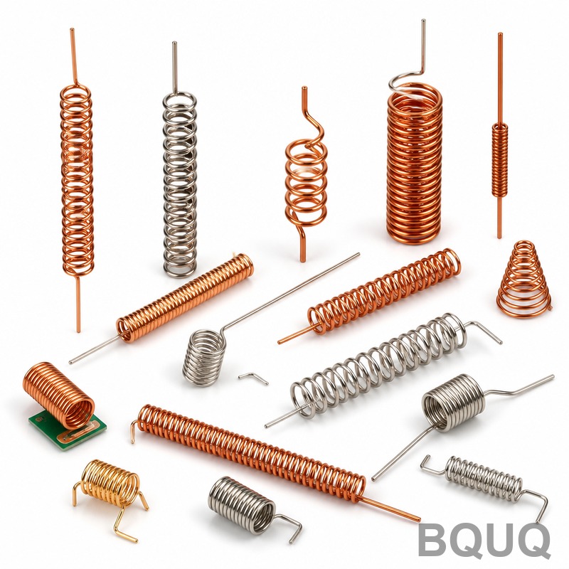
Torsion Spring Body Diameter and Clearance
Short answer: Size the torsion spring body diameter so the mandrel or shaft leaves 5–10% of the inside diameter as running clearance — typically 0.2–0.5 mm on a 10 mm ID — and remember the body shrinks as the spring winds up. A torsion spring wound to reduce diameter under load must never bind on its mandrel, or torque rises unpredictably and the legs fatigue. At BQUQ we machine and wind to a ±0.005 mm CNC envelope, hold body diameter to roughly ±0.15 mm on typical wire sizes, and return torsion spring quotes in 12 working hours. Flexible MOQ means you can validate clearance on a real assembly before committing to volume.
Why Torsion Spring Body Diameter Is Not Just a Catalog Number
A torsion spring is a helical coil that resists rotation rather than compression or extension. The body diameter — the outside diameter (OD) of the wound coil, or the inside diameter (ID) of the bore it creates — is the single dimension that most often decides whether a design works on the bench or jams in the field.
Three things make torsion spring diameter harder to pin down than compression spring diameter:
1. The spring winds up. As the legs rotate toward each other, the coil either grows or shrinks depending on winding direction. A spring wound in the direction of applied torque closes down on its mandrel; wound against it, the coil opens.
2. The mandrel is a hard constraint. Unlike a compression spring sitting in a free bore, a torsion spring usually rides on a shaft or pin that cannot move. If the coil closes onto that pin, friction and interference spike immediately.
3. Leg geometry eats tolerance. Body diameter, leg length, leg angle, and free position all interact. A body that is 0.3 mm oversize can push the legs out of alignment with the mating feature.
For buyers sourcing torsion springs from a factory, the practical question is: what body diameter do I specify, and what clearance do I leave?
How Does Winding Direction Change Body Diameter Under Load?
This is the first thing to settle, because it determines whether your clearance budget grows or shrinks during operation.
The two winding cases
| Winding vs. applied torque | Coil behavior under load | Mandrel clearance trend |
|---|---|---|
| Wound in direction of torque (spring "closes") | Body diameter decreases | Clearance shrinks — must be verified at max deflection |
| Wound against direction of torque (spring "opens") | Body diameter increases | Clearance grows — mandrel fit is set by free-state ID |
If you are unsure which case applies, look at the legs: applying torque that pulls the legs together on a spring wound so the coils tighten is the closing case. Many assemblies accidentally use the closing configuration because it produces a stiffer, more compact package — and then bind on the shaft.
Typical diameter change
For a torsion spring with a spring index (D/d, body diameter divided by wire diameter) between 6 and 12, the body diameter change at full deflection is typically in the range of 2–6% of the free body diameter. That is indicative, not a guarantee — it scales with deflection angle, index, and material modulus.
On a 10 mm free ID closing by 4%, you lose 0.4 mm of clearance. If you only allowed 0.3 mm, the spring is now an interference fit on its mandrel.
What Clearance Should You Leave Between Spring and Mandrel?
There is no universal number, but there is a reliable starting range.
| Application | Recommended diametral clearance (ID to mandrel) | Notes |
|---|---|---|
| Static or low-cycle, closing wind | 8–12% of ID | Generous because ID shrinks under load |
| Static or low-cycle, opening wind | 5–8% of ID | ID grows; less risk of bind |
| Dynamic, high cycle, closing wind | 12–15% of ID | Add margin for wear, debris, thermal growth |
| Precision instrument, tight package | 3–5% of ID | Only with verified max-deflection ID and polished mandrel |
| Corrosive or dirty environment | 10–15% of ID | Debris bridges small gaps and causes galling |
For a 10 mm ID closing-wind spring in a general industrial application, that puts you around 0.8–1.2 mm diametral clearance — meaning a mandrel of roughly 8.8–9.2 mm. Many engineers instinctively tighten this to 0.1–0.2 mm for "precision" and then fight binding in the field.
Why tighter is not better
Excessively tight clearance causes:
- Friction torque that adds to spring torque and drifts with lubrication state
- Galling between spring wire and mandrel, especially in stainless
- Fatigue initiation at the contact points where the coil rubs
- Assembly damage — a tight torsion spring is usually pressed on, which distorts the body
The mandrel should guide the spring, not grip it. If you need radial location, use the legs and end features, not the body-to-mandrel fit.
How Do You Calculate the Free Body Diameter to Specify?
Work backwards from the mandrel.
1. Fix the mandrel diameter from your shaft, pin, or boss. This is usually set by strength and bearing requirements, not by the spring.
2. Choose clearance from the table above based on winding direction and duty cycle.
3. Compute the minimum operating ID = mandrel diameter + clearance.
4. Convert to free ID by adding back the expected closure at max deflection.
5. Convert to free OD = free ID + 2 × wire diameter.
6. Set the tolerance — typically ±0.15 mm on body OD for wire diameters up to about 2 mm, tighter on request.
Worked example
| Step | Value |
|---|---|
| Mandrel diameter | 9.00 mm |
| Duty | Dynamic, closing wind |
| Clearance target | 12% of ID |
| Minimum operating ID | 10.20 mm |
| Expected closure at max deflection | 4% of free ID |
| Free ID | 10.20 / 0.96 = 10.63 mm |
| Wire diameter | 1.20 mm |
| Free OD | 10.63 + 2.40 = 13.03 mm |
| Specify | OD 13.0 mm ±0.15 mm, right-hand wind, closing |
This is the kind of arithmetic that belongs in your drawing notes. If you hand a supplier only an OD and a wire size, the winding direction and clearance intent are lost — and the spring index and stress relationship that governs fatigue life goes unchecked.
Which Tolerances Actually Matter on a Torsion Spring Body?
Body diameter tolerance is only one of several stacked tolerances. Buyers who specify body OD alone often find the assembly still fails.
| Feature | Typical tolerance | Why it matters |
|---|---|---|
| Body OD / ID | ±0.15 mm (indicative) | Mandrel fit, radial space |
| Wire diameter | ±0.02 mm to ±0.03 mm | Torque rate, body diameter stack |
| Free angle between legs | ±2° to ±5° | Preload position, leg alignment |
| Leg length | ±0.3 mm | Mating slot engagement |
| Number of coils | ±0.25 coil | Rate and body length |
| Body length | ±0.3 mm | Axial space, end clearance |
Note that body OD tolerance and wire diameter tolerance compound. If wire runs 0.03 mm over and the winder holds nominal, the OD grows 0.06 mm. This is why spring length tolerance and diameter tolerance should be specified together, not in isolation.
Squareness and end conditions
Torsion springs with closed, ground ends behave differently from open-ended coils. Ground ends give a flatter axial face and better body-length control, but grinding can introduce a small burr on the ID that reduces effective clearance. If your clearance budget is under 5%, specify deburred or tumbled ends.
What Materials and Finishes Affect Body Diameter?
Material choice changes both the free diameter and how much it moves under load.
- Music wire (ASTM A228): high modulus, predictable, good for small bodies. See our notes on spring material music wire.
- Stainless (302/304, 17-7PH): lower modulus than carbon steel, so slightly more diameter change at the same stress; also more prone to galling on a mandrel.
- Phosphor bronze and beryllium copper: non-magnetic and conductive options, with lower modulus and larger diameter change.
- Coatings: zinc, nickel, and epoxy add 5–25 µm per surface, which reduces ID clearance. Always specify whether the diameter is measured before or after coating.
For stainless torsion springs running on stainless mandrels, add 2–3% extra clearance and consider a dry-film lubricant or a bronze bushing to break the like-on-like galling couple. BQUQ runs corrosion-resistant stainless grades as standard; we do not claim certifications beyond ISO9001.
Design Mistakes That Cause Torsion Spring Binding
These come up repeatedly in RFQ reviews.
1. Specifying OD only. The mandrel cares about ID. Give both, or give ID and wire diameter.
2. Ignoring winding direction. A "closing" spring on a tight mandrel is the most common field failure we see.
3. Assuming the spring is round. A torsion spring wound on a mandrel with too little tension can come off slightly oval, especially at low spring index.
4. Forgetting thermal growth. Aluminum housings and steel mandrels move differently over a 60 °C swing; 0.05–0.1 mm of clearance can vanish.
5. No preload definition. Torsion springs are usually installed with some angular preload. That preload already consumes part of the clearance budget.
6. Mixing up free angle and installed angle. The body diameter at installed angle is not the free diameter.
When you send a custom spring RFQ, include mandrel diameter, winding direction, installed angle, max deflection angle, and duty cycle. Those five data points let a factory size the body correctly the first time.
How BQUQ Manufactures and Verifies Torsion Spring Bodies
BQUQ (Dongguan) runs four production lines in one factory covering CNC machining, metal stamping, custom springs, and heat sink production. For torsion springs that means:
- Wire forming and coiling on CNC spring machines with programmable pitch, wind direction, and leg angle
- In-house CNC mandrels and fixtures machined to ±0.005 mm, so test mandrels match your production shaft
- First-article inspection reporting body OD, ID, free angle, leg length, and rate
- Flexible MOQ — prototype quantities through production volumes
- 12 working hours for a quote on a complete drawing
Because the mandrel and the spring come from the same factory, we can verify clearance on a matched pair rather than guessing. That is the practical advantage of a source-direct supplier with both machining and spring winding under one roof.
If your assembly also uses compression or extension springs, the same clearance logic applies — see compression springs and extension custom springs for the equivalent diameter and clearance rules.
Frequently Asked Questions
Q: What is the ideal clearance between a torsion spring and its mandrel?
A: For a closing-wind torsion spring, allow roughly 8–12% of the inside diameter as diametral clearance; for opening-wind, 5–8% is usually sufficient. On a 10 mm ID that means a mandrel around 8.8–9.2 mm. Dynamic or dirty-environment applications should sit at the upper end of the range, and precision instrument designs can go as low as 3–5% only when maximum-deflection ID has been verified.
Q: Does torsion spring body diameter change when the spring is loaded?
A: Yes. A spring wound in the direction of applied torque closes down on its mandrel, typically reducing body diameter by 2–6% of free diameter at full deflection for spring indexes between 6 and 12. A spring wound against the torque direction opens instead. Always verify clearance at maximum deflection, not at the free state, because that is where binding occurs.
Q: Should I specify torsion spring OD or ID on my drawing?
A: Specify both, plus wire diameter and winding direction. The mandrel fit is governed by ID, while radial envelope space is governed by OD. Giving only OD leaves the supplier to infer ID from wire diameter, and any wire tolerance then shifts the fit. Include free angle, leg length, installed angle, and maximum deflection angle so the body can be sized correctly.
Q: How tight can torsion spring diameter tolerances be?
A: Typical production tolerance on body OD is around ±0.15 mm for wire diameters up to roughly 2 mm, with tighter capability available on request. Wire diameter itself typically runs ±0.02–0.03 mm, and those two tolerances stack. If your clearance budget is under 5% of ID, discuss the tolerance stack with your supplier before releasing the drawing to production.
Q: What causes a torsion spring to bind on its shaft?
A: The usual causes are insufficient clearance for the closing-wind diameter reduction, a mandrel that is too tight for "precision," like-on-like galling between stainless spring and stainless shaft, thermal growth closing the gap, or an installed preload that already consumes the clearance budget. Increasing clearance to 10–12% of ID and adding a lubricant or bushing resolves most field binding cases.
Related Resources
- About BQUQ and our Dongguan factory: /about/
- Torsion springs, compression springs, and extension springs: /torsion-springs/, /compression-springs/
- Industry trends in spring and metal component sourcing: /industry-dynamics/
- Technical articles on spring design and tolerances: /bquq-blog/
- Frequently asked questions for B2B buyers: /faq/
- Case studies from precision manufacturing projects: /case/
- Contact the engineering team for a 12-hour quote: /contact/
Authored by the BQUQ Engineering Team. BQUQ (Dongguan) runs CNC machining (±0.005 mm), metal stamping, custom springs, and heat sink production in one ISO9001 factory. Source-direct from Dongguan, China — quote in 12 hours: sc@bquq.com | WhatsApp +86 13713157787 | www.bquq.com


