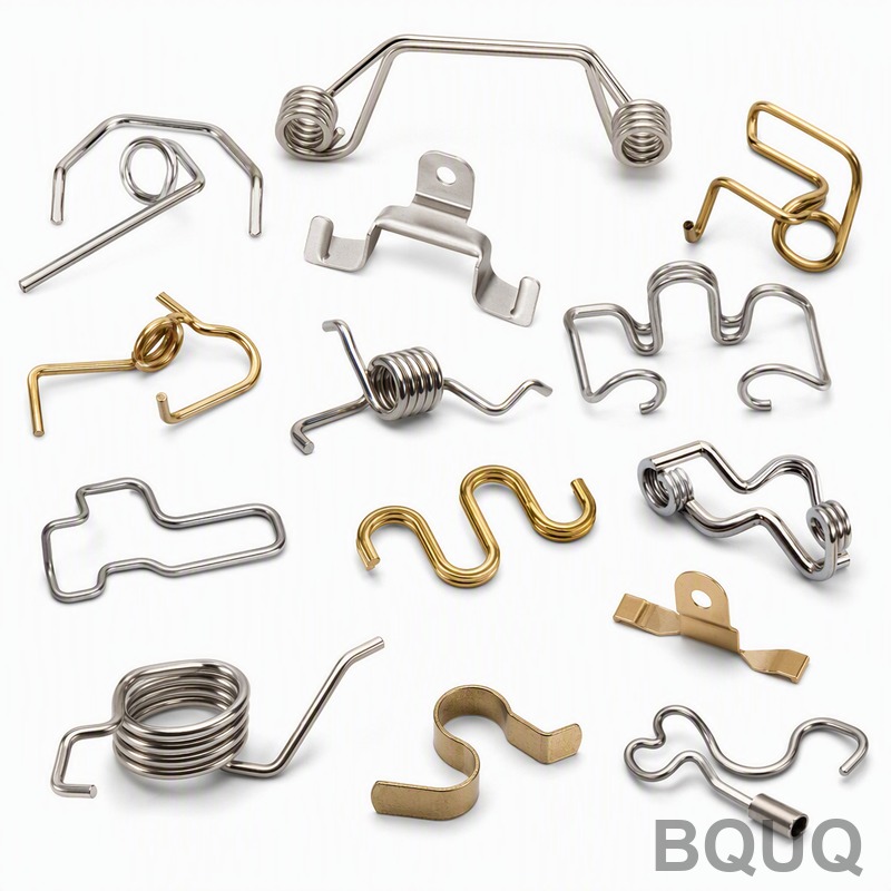
Sensor Socket Wire Form Spring: 302 Stainless Steel, 0.5mm, ±0.05mm
A sensor socket contact is where electrical reliability and mechanical precision meet. The part is a three-dimensionally formed wire clip: it must spring into position inside the socket, deliver a consistent normal force against the sensor pin, and keep doing it through insertion after insertion over the life of the device. If the forming geometry drifts or the contact force scatters, the symptom is an intermittent signal - the most expensive kind of field failure to diagnose.
Project Background & Challenge
The customer is a European manufacturer of industrial sensors used in factory automation and process monitoring. Their sensor family uses a small wire-formed contact spring inside the connection socket to grip the mating pin. The design demands two things at once from a single 0.5mm wire: geometry accurate enough to locate the contact exactly where the socket designer intended, and a spring force stable enough to guarantee low contact resistance across hundreds of thousands of sockets.
Their previous source struggled with exactly this combination. The three-dimensional forming tolerance was set at ±0.05mm on the critical bend positions - far tighter than general wire-form bending can casually deliver - and batches showed form drift that moved the contact point and changed the insertion feel. Worse, contact force varied part to part by well beyond the ±5% consistency the socket design assumed, producing sockets that tested fine at assembly but developed intermittent readings after thermal cycling in the field.
There was also a finishing dimension to the problem. The cut end of the wire sits close to the contact zone, and any burr risks scratching the pin plating or shedding debris into the socket. The customer therefore specified deburring plus nickel plating, with the plating expected to keep contact resistance low and stable, not merely to look corrosion-protected. Volume ranged from 200,000 to 800,000 pieces per month across several socket variants, which meant the process had to survive frequent changeovers without losing control.
Before approaching BQUQ, the customer had considered redesigning the socket around a stamped contact strip instead. That path would have required new tooling and a longer qualification cycle for a running product family. The wire-form route was worth one more attempt because it preserved the existing socket design, provided the two tolerances could genuinely be held at volume - which became the acceptance test for the whole project.
BQUQ Process Solution
BQUQ broke the problem into three controlled steps: hold the 3D geometry, finish the part so the contact zone stays clean, and measure force as a first-class characteristic rather than a by-product of bending.
CNC 3D Wire Forming & Tooling
The contacts are formed on CNC wire forming equipment from 0.5mm 302 stainless steel wire - a material and diameter squarely inside BQUQ's spring wire range of 0.2-3mm. Dedicated tooling was built for each bend sequence, and the critical bend positions were verified on the optical projector against the ±0.05mm tolerance, sampled at the start, at intervals during the run and at the end. Because 302 wire has slight springback, the tooling was compensated iteratively during development until the formed geometry landed centered in the tolerance band, not merely inside it.
Deburring & Nickel Plating
After forming and cutoff, every part goes through deburring to eliminate the sharp tail edge and any burr that could damage the pin plating or generate loose particles. Nickel plating is then applied with thickness controlled for wear resistance and stable contact resistance. Sample parts from each plating lot are checked for coating thickness, and contact resistance is measured before and after plating to confirm the finish contributes to, rather than compromises, the electrical performance of the socket.
Contact Force Consistency Control
Contact force is measured with a force gauge on a sampling plan tied to batch size, with the ±5% consistency requirement treated as the primary release criterion - a socket with perfect geometry but weak force is a reject. Force data is charted across each run under SPC, and when the program shifts between socket variants, the first hours of the new setup run under intensified sampling until the distribution re-centers. This is what allows the part to move between variants at monthly volumes of 200K-800K pieces without the force scatter creeping back.
Three-dimensional wire forming is where this part earns its tolerance band. Each bend is programmed with springback compensation measured per wire lot, because 302 stainless from different mills relaxes differently after forming. First articles are scanned against the 3D model, and forming fixtures are re-qualified whenever the wire supplier or lot changes. Contact force is set by bend angle and leg length rather than by adjustment at assembly, so the ±5% force window is held at the former, not patched later. After forming, parts are deburred in a vibratory finish that rounds wire ends without flattening them, then nickel plated to keep contact resistance stable through humidity cycling.
Key Specifications
| Item | Specification |
|---|---|
| Material | 302 stainless steel spring wire |
| Wire diameter | 0.5mm |
| 3D forming tolerance | ±0.05mm on critical bend positions |
| Contact force consistency | ±5%, SPC-monitored per batch |
| Surface finish | Deburred, nickel plated |
| Volume | 200K-800K pcs/month across socket variants |
| Inspection | Optical projector layout, force gauge sampling, CPK≥1.33, ISO9001:2015 |
| Delivery | Samples 3-7 days; first batch 12-20 days |
Quality Control & Delivery
Each new setup starts with a first-article approval: a full layout of all bend positions on the optical projector, force testing on a statistically meaningful sample, plating thickness, and a contact-resistance check against the customer's limit. In serial production, geometry and force are the two SPC characteristics, both tracked with CPK≥1.33, and each shipment carries an inspection report under the ISO9001:2015 quality system. Retained samples from every lot are archived so that any field question can be answered against the actual parts, not a memory of them.
Result: the ±0.05mm forming tolerance and ±5% force consistency were both demonstrated during qualification and have held through production. The customer has since moved two additional socket variants for the same sensor family to BQUQ, and field complaints attributable to socket contact - the original driver of the project - have not recurred.
Changeover discipline deserves mention as part of the result. With several socket variants sharing the same wire diameter, tooling sets are stored and identified per variant, and every changeover is followed by the intensified sampling window described above. That procedure turned what used to be the riskiest moment of the program - the switch between variants - into a routine event measured in hours.
Related Products & Resources
For other formed-spring formats, browse the Custom Torsion Springs and the Steel Torsion Spring Collection.
To learn more about BQUQ's engineering and quality organization behind these parts, visit About BQUQ.
FAQ
How accurate can 3D wire forming be?
For this part, critical bend positions are held at ±0.05mm, verified on the optical projector at defined points in every run. Accuracy comes from compensating the tooling for springback during development and then locking the setup, with intensified sampling after every variant changeover.
What wire diameters and materials do you form?
Wire from 0.2mm to 3mm in 302/304 stainless steel, 65Mn, music wire and phosphor bronze, covering torsion springs, coil springs and three-dimensional wire forms. This project's 0.5mm 302 stainless wire is a routine size with well-characterized springback.
How do you keep contact force consistent across a batch?
Force is treated as the primary release criterion with ±3-5% tolerance capability. Samples are measured with a force gauge on a batch-tied sampling plan, charted under SPC, and CPK≥1.33 is required on force before shipment - so consistency is demonstrated with data, not assumed.
What does the nickel plating actually do here?
Two jobs: protect the 302 stainless contact against corrosion in industrial atmospheres, and keep contact resistance low and stable over the socket's life. Parts are deburred before plating so no burr scratches the mating pin, and plating lots are checked for thickness and resistance before release.