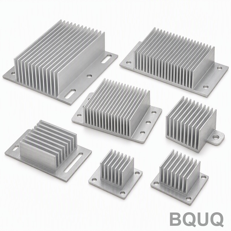
VFD Inverter Extruded Heatsink with CNC Machined Mounting Base: 6063-T5, 1.0mm Fins, 0.05mm Flatness, 8K-30K pcs/month
A power-stage heatsink for a variable frequency drive looks like a simple extrusion, but that is exactly where most projects go wrong. The extrusion is only half the part: the IGBT mounting face must be machined flat to within hundredths of a millimeter, fan mounting holes must line up across thousands of units, and the whole thing has to repeat month after month at volumes between 8,000 and 30,000 pieces. Extrusion alone cannot deliver that; this case shows how a two-process workflow solved it.
Project Background & Challenge
The customer is a variable frequency drive manufacturer in South China. Their drive product line uses an aluminum heatsink as both the thermal path and the structural base of the power section: IGBT modules bolt directly onto the machined base face, cooling fans bolt onto a pattern of holes at the fin side, and the entire assembly is mounted into the drive enclosure through features on the same part. One component, three functions, and no room for rework at their production rate.
Before coming to us, they were buying the extrusion from one supplier and sending it to a second shop for machining. The arrangement created three recurring problems. First, the IGBT mounting face flatness drifted between batches - anything above their 0.05mm requirement meant thermal interface material gaps, hot spots, and field failures they could not afford. Second, the fan mounting holes, toleranced at ±0.1mm for position, occasionally missed alignment with the fan bracket, forcing manual rework on the assembly line. Third, managing two suppliers doubled the logistics chain: every transport batch was an opportunity for surface damage on the exposed fins, and any quality dispute had nowhere obvious to land.
The technical difficulty is real and worth stating plainly. A 6063-T5 profile with 1.0mm fins is a long, flexible part - it will not survive aggressive clamping without bowing. Machining the base flat while the part is stressed from extrusion and handling means the flatness you measure on the machine disappears when the part is released. The customer needed a supplier who understood both the extrusion side and the machining side, and could hold 0.05mm flatness repeatably at up to 30,000 pieces a month.
BQUQ Process Solution
Our answer was a single-source, two-process workflow: purpose-designed extrusion feeding directly into a dedicated CNC facing operation, with stress management designed into the sequence rather than inspected in at the end.
Extrusion Design and Die Control
The profile was engineered around the thermal requirement first: 1.0mm fin thickness, fin pitch optimized for the customer's airflow from the fan layout, and a solid base section thick enough that machining the IGBT face would not weaken the structure. Extrusion is scheduled on qualified partner lines that we audit, with die maintenance on a fixed schedule so fin thickness and straightness stay consistent across the monthly volume. Billets are 6063-T5 throughout, chosen for extrudability, thermal conductivity, and the way it responds to black anodizing. After extrusion, every profile passes through straightening and is cut to length with the machining datum features preserved - so the CNC stage receives a consistent input, batch after batch.
CNC Machining of the IGBT Mounting Base and Fan Holes
Machining is scheduled on CNC machining centers set up specifically for this family of parts. The workholding is the critical decision: long flexible extrusions are clamped on the fin tips through a compliant interface that supports the profile without point-loading it, and the IGBT face is machined in a single facing pass per zone. Because the profile arrives with consistent datums, the facing operation removes a controlled, small amount of stock - enough to guarantee a fully machined surface, small enough that stress redistribution does not pull the face out of flat after unclamping.
The IGBT mounting face is held to 0.05mm flatness, verified with a flatness check on a granite surface plate for every first article and sampled per batch. The fan mounting holes are drilled and chamfered in the same setup, holding ±0.1mm on hole position against the customer's fan bracket drawing - one setup for both feature groups means no re-clamping error between them. Enclosure mounting features are finished in the same cycle, so the part goes from machine to anodizing as a complete component.
Black Anodizing and Final Protection
After machining, parts are black anodized. The anodic layer adds a controlled growth on the IGBT face, which matters when the customer specifies a surface finish for thermal contact - so the machining allowance was set to land the final finish inside specification after anodizing, not before. Black anodizing also gives the fin field a high-emissivity surface that improves radiant heat rejection and matches the drive's interior aesthetics. Machined mating faces are protected during anodizing per the customer's drawing, and parts are packed fin-tip-first in divided trays so the 1.0mm fins arrive undamaged.
Key Specifications
| Item | Specification |
|---|---|
| Material | 6063-T5 aluminum extrusion |
| Fin thickness | 1.0mm extruded fins, pitch optimized for forced-air cooling |
| IGBT mounting face | CNC machined, flatness 0.05mm, finish per drawing for thermal contact |
| Fan mounting holes | Position tolerance ±0.1mm, drilled and chamfered in the same setup as the base face |
| Surface finish | Black anodized, machined faces protected per drawing |
| Volume | 8,000-30,000 pcs/month on rolling schedules |
| Inspection | Flatness check on granite plate, hole position with CMM sampling, first-article full layout |
| Delivery | Samples 3-7 days, first production batch 12-20 days |
Quality Control & Delivery
Quality control starts before machining. Incoming profiles are checked for fin geometry and straightness; the first article of every new die lot receives a full dimensional layout including the 0.05mm flatness check on the IGBT face. In production, hole positions are sampled on a CMM, flatness is spot-checked on a granite plate, and the data feeds a monthly CPK review with the customer - all under our ISO9001:2015 quality system. Because extrusion and CNC scheduling sit under one project owner, a dimensional drift is traced to its source in hours instead of a two-supplier finger-pointing exercise in weeks.
The delivery result: samples within 3-7 days of drawing approval, first production batch in 12-20 days, and monthly rolling shipments ever since across the 8K-30K volume band. Flatness acceptance on the IGBT face has held at 0.05mm batch after batch, fan hole alignment issues on the customer's assembly line dropped to zero, and the single-source workflow removed an entire transport leg - along with the fin-damage claims that came with it. The customer has since transferred two additional drive heatsinks from the same product family onto the same workflow.
Related Products & Resources
If you are sourcing a similar power-stage heatsink, these pages show how we package this workflow:
- Custom Aluminum Heatsink with Mounting Base - the exact family this case belongs to
- Custom Extruded Aluminum Heatsinks - profile design and extrusion capability
For tolerance tables, anodizing options and lead-time details, see the BQUQ FAQ Center.
FAQ
Can you really hold 0.05mm flatness on the IGBT mounting face at 30K pcs/month?
Yes, and the two numbers are related. The facing pass removes a small, controlled amount of stock in one setup, the workholding supports the profile instead of squeezing it, and every first article is verified with a flatness check on a granite plate. Batch sampling plus monthly CPK review keeps the process honest across volumes up to 30,000 pieces a month.
Why 1.0mm fins instead of thinner fins for more surface area?
Fin thickness is a trade-off. Fins below 1.0mm extrude with higher scrap risk and arrive more prone to bending in handling, while 1.0mm at the customer's fan-driven pitch already delivered the thermal resistance target. Extruded fins from 0.3mm upward are available when the thermal calculation genuinely calls for them.
How fast can you deliver the first batch?
Typical flow for this family: samples in 3-7 days after drawing approval, first production batch in 12-20 days, then monthly rolling schedules. For a repeat part with an existing die, the first batch frequently lands at the 12-day end of that window.
What does the black anodizing do for a heatsink - is it just cosmetic?
It is functional. Black anodizing raises the surface emissivity of the fin field, which improves radiant heat rejection alongside forced-air convection, and it adds corrosion resistance for the drive's operating environment. The layer thickness is accounted for in the machining allowance so the IGBT face still meets the specified finish and flatness after anodizing.