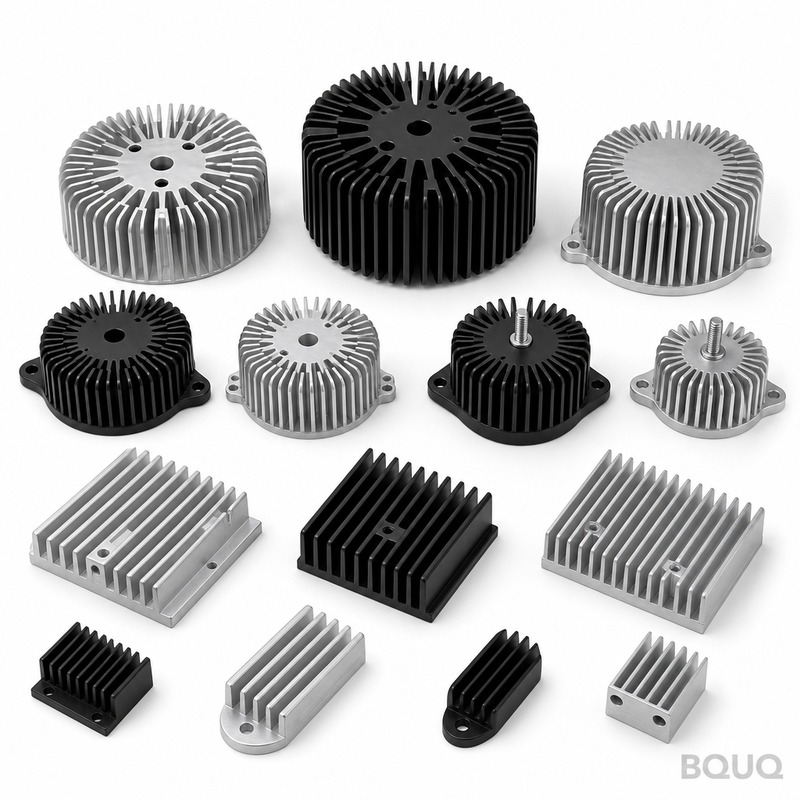
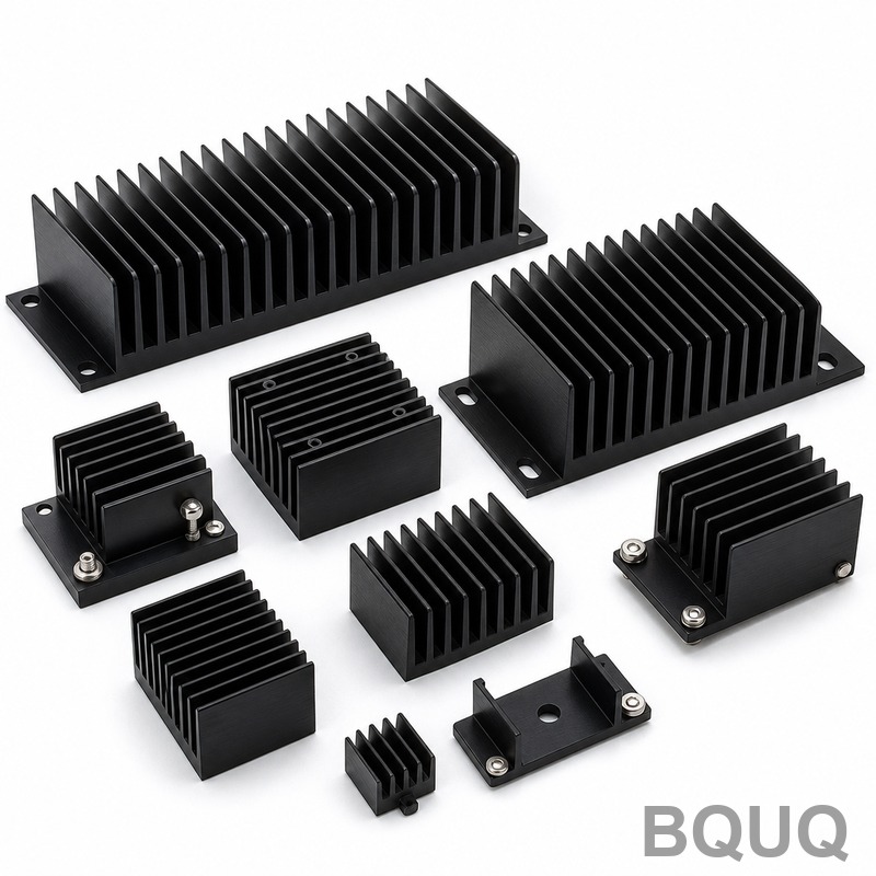
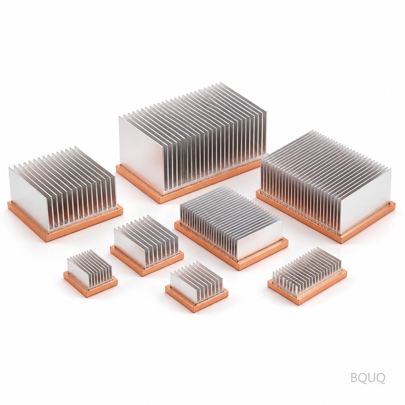
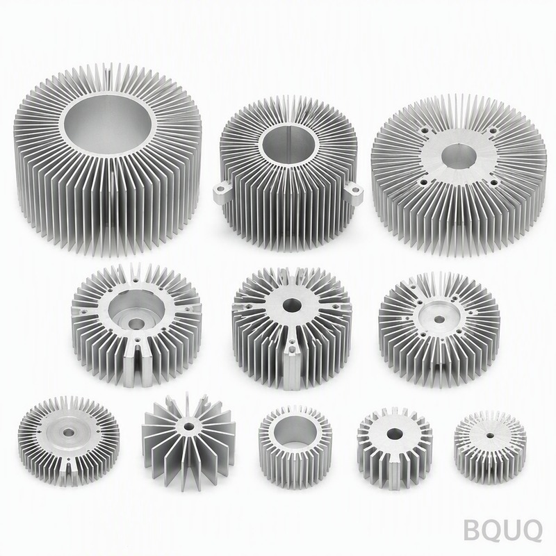
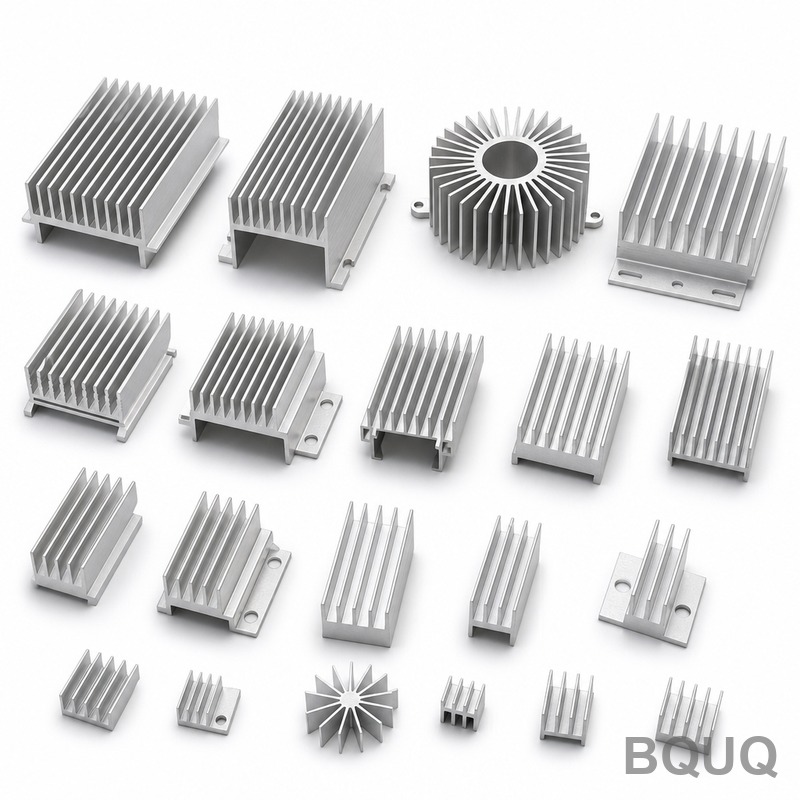
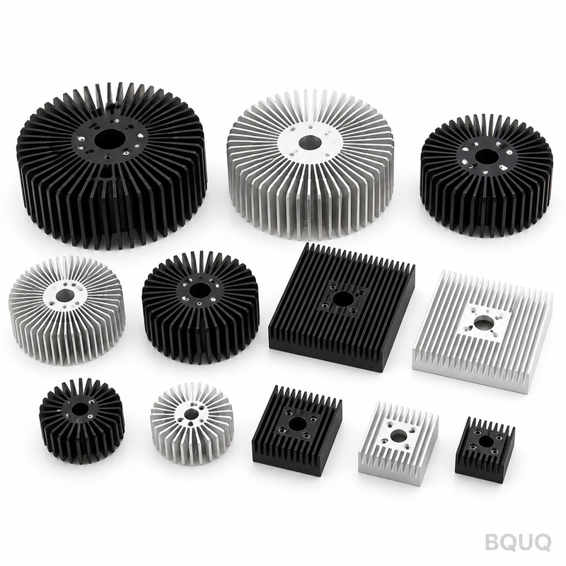
heat sinks: copper-alloy CuZn37, 0.3 mm fins at 1.5 mm pitch, 0.15 mm over 100 mm flatness, 0.35 K/W thermal resistance. MOQ 50 pcs, ships in 72 hours.
heat sinks
heat sinks: copper-alloy CuZn37, 0.3 mm fins at 1.5 mm pitch, 0.15 mm over 100 mm flatness, 0.35 K/W thermal resistance. MOQ 50 pcs, ships in 72 hours.
Get a Fast Quote for This Part
Send us your drawing / quantity / material — reply within 24h.
Heat sinks in copper-alloy CuZn37 deliver 0.35 K/W thermal resistance under ΔT = 75 K with forced air at 2.0 m/s. Fins are 0.3 mm thick at 1.5 mm pitch over a 3.0 mm base. Stamping holds pitch within ±0.05 mm across an 800,000 pcs run, with an 18 s cycle on a 110 T press and ±0.10 mm hole position.
Heat sinks in copper-alloy CuZn37 deliver 0.35 K/W thermal resistance under ΔT = 75 K with forced air at 2.0 m/s. Fins are 0.3 mm thick at 1.5 mm pitch over a 3.0 mm base. Stamping holds pitch within ±0.05 mm across an 800,000 pcs run, with an 18 s cycle on a 110 T press and ±0.10 mm hole position.
A heat sinks in copper-alloy CuZn37 delivers 0.35 K/W thermal resistance under ΔT = 75 K, forced air 2.0 m/s. Fins are 0.3 mm thick at 1.5 mm pitch over a 3.0 mm base, and every batch ships with a CMM report at CMM plus granite flatness plate.
Design Approach and Process
Stamping gives a repeatable 0.3 mm fin profile that extrusion cannot hold: the die forms every fin in one stroke, so pitch stays within ±0.05 mm across a 800,000 pcs run.
A single 110 T stroke forms the whole heat sinks, so part cost stops scaling with complexity. Tooling runs ±0.05 mm, and the 18 s cycle feeds a 800,000 pcs line.
One supplier now covers 0.3 mm to 0.3 mm fin gauges from the same 110 T press family, so a thermal redesign is a tooling change rather than a new vendor.
Pressing copper-alloy CuZn37 keeps the heat sinks light, from 280 g depending on envelope, without sacrificing fin density, which matters where airflow path length is already fixed by the enclosure.
Every stroke is dimensionally identical, so ±0.10 mm hole position carries across the batch. That is what makes EV and OBC charger volume programs repeatable.
The standard material is copper-alloy CuZn37, supplied with black anodize Type II, 10-15 µm. For applications where EV and OBC charger exposure is a concern, we recommend the passivated route; where conductivity matters more than weight, copper C110 raises thermal performance and roughly doubles unit mass.
Tolerance Classes You Can Specify
General dimensions run to ±0.15 mm, with critical features such as ±0.05 mm on base thickness held separately. Formed geometry inherits tooling repeatability of ±0.05 mm, and hole position is held to ±0.10 mm. Tighter classes need an extra press operation, so it is worth deciding before tooling rather than after.
Inspection Before Every Shipment
Flatness is checked on a granite surface plate, 20 °C against a 0.15 mm over 100 mm limit, and fin pitch is verified optically at ±0.05 mm. Reports go out with each lot.
Each batch carries a CMM report from CMM plus granite flatness plate. We record flatness, pitch, base thickness and hole position, and flag anything outside ±0.15 mm before it leaves the line.
Lot traceability runs from coil to carton: heat number, press stroke range and inspection record stay attached, so a field issue can be tied back to a specific run.
Flatness is measured on granite rather than on cast iron, because 0.15 mm over 100 mm at 120 x 80 x 50 mm reads differently on a plate that has not been lapped. Records keep both readings.
Where This Part Is Used
In EV and OBC charger, the 0.35 K/W rating determines how much airflow the enclosure still needs. At EV and OBC charger junction temperatures, 0.3 mm fins at 1.5 mm pitch keep the delta-T inside the sensor budget.
EV and OBC charger packaging and vibration rules push toward one-piece construction. A stamped heat sinks has no adhesive to creep, which is the usual failure mode in two-part coolers.
EV and OBC charger designs often run a 2.0 m/s forced-air path. 0.35 K/W at ΔT = 75 K, forced air 2.0 m/s means EV and OBC charger can hold its target with fan power below the acoustic limit.
For EV and OBC charger prototypes, 72 hours covers drawing review and first article. Production lots move to 12 working days once the ±0.05 mm capability is signed off.
Specifications
Parameter
Value / Range
Material
copper-alloy CuZn37
Fin thickness
0.3 mm
Fin pitch
1.5 mm
Fin height
50 mm
Base thickness
3.0 mm
Base flatness
0.15 mm over 100 mm
Thermal resistance
0.35 K/W
Thermal test condition
ΔT = 75 K, forced air 2.0 m/s
Surface finish
black anodize Type II, 10-15 µm
Size range
120 x 80 x 50 mm
FAQ: Your Questions Before Ordering
Which materials do you recommend?
copper-alloy CuZn37 is the standard choice. For EV and OBC charger in a corrosive environment we specify 6063-T5 with black anodize Type II, 10-15 µm; for the highest conductivity we move to copper C110, which raises cost and weight but drops thermal resistance by roughly half at the same envelope.
Do you make the heat sinks in different sizes?
The family covers 120 x 80 x 50 mm, with unit weights from 280 g. Because the base is pressed, new sizes are a die insert change rather than a new press line, so development is usually 2 weeks rather than 8.
What quality certifications do you hold?
The plant is ISO9001 certified, and parts ship with RoHS and REACH declarations on request. Third-party SGS inspection can be arranged before the container is sealed, which is what most EV and OBC charger buyers specify.
Can you help with thermal simulation before sampling?
Yes. Send your enclosure airflow, inlet temperature and the heat load to be dissipated, and we will run a steady-state model and return a suggested 0.3 mm and 1.5 mm combination. That usually saves one tooling iteration.
What is the difference between your heat sinks and a skived fin heat sinks?
Skived fins are milled, so you get thin, tall fins and higher density in a given height, but the cost scales directly with fin area. Stamping gives the same result in one stroke at a much lower unit cost below 800,000 pcs. For EV and OBC charger in a fixed-height enclosure, stamped is normally the right answer.
How We Manufacture and Ship
The factory holds ISO9001 and can ship RoHS and REACH documentation with the Anti-static bag + wooden crate over 50 kg. Third-party SGS inspection is arranged on request before the container is sealed.
Quality staff sit beside the press, not in a separate room. Deviations on 1.5 mm or 0.15 mm over 100 mm stop the run at the tool rather than at final inspection.
We quote FOB Guangzhou and hold 50 pcs for sampling. Sampling is sample fee 30-80 USD, so a first evaluation does not require a production commitment.
What thermal resistance can I expect from a CuZn37 heat sink?
A copper-alloy CuZn37 heat sink delivers 0.35 K/W thermal resistance under ΔT = 75 K with forced air at 2.0 m/s. Fins are 0.3 mm thick at 1.5 mm pitch over a 3.0 mm base, and every batch ships with a CMM report.
How tight is the fin pitch tolerance on stamped heat sinks?
Stamping holds fin pitch within ±0.05 mm across an 800,000 pcs run. The die forms every fin in one stroke on a 110 T press, so pitch stays repeatable even at 0.3 mm fin thickness and 1.5 mm pitch.
What is the cycle time and production capacity for these heat sinks?
The 18 s cycle feeds an 800,000 pcs line. A single 110 T stroke forms the whole heat sink, so part cost stops scaling with complexity. Tooling runs ±0.05 mm, and hole position carries at ±0.10 mm across the batch.
Can I switch from extrusion to stamping without changing vendors?
Yes. One supplier now covers 0.3 mm to 0.3 mm fin gauges from the same 110 T press family, so a thermal redesign is a tooling change rather than a new vendor. Stamping gives a repeatable 0.3 mm fin profile that extrusion cannot hold.
What material and weight range are available for these heat sinks?
The standard material is copper-alloy CuZn37. Pressing it keeps the heat sink light, from 280 g depending on envelope, without sacrificing fin density. This matters where airflow path length is already fixed by the enclosure.
How is hole position controlled across a high-volume batch?
Every stroke is dimensionally identical, so ±0.10 mm hole position carries across the batch. That is what makes EV and OBC charger volume programs repeatable. Each batch also ships with a CMM report at CMM plus granite flatness plate.
What inspection records come with each heat sink shipment?
Every batch ships with a CMM report at CMM plus granite flatness plate. Inspection before every shipment covers fin pitch, hole position, and thermal resistance. The 0.35 K/W at ΔT = 75 K and 2.0 m/s forced air is verified per batch.
Key Specifications and Selection Guide
Spec comparison
Parameter
Value / Range
Material
Copper-alloy CuZn37
Tolerance
Pitch ±0.05 mm; hole position ±0.10 mm
Lead time
Not specified in excerpt
MOQ
Not specified in excerpt
Capacity
800,000 pcs run; 18 s cycle on 110 T press
Selection / comparison
Option
Best for
Trade-off
Stamped CuZn37 heat sinks
High-volume runs needing 0.3 mm fins at 1.5 mm pitch
Tooling change required for thermal redesign
Extruded heat sinks
Simple profiles with thicker fins
Cannot hold 0.3 mm fin profile repeatably
Stamped heat sinks from same 110 T press family
Fin gauges from 0.3 mm to 0.3 mm
Limited to press capacity and tooling
Copper-alloy CuZn37
Lightweight heat sinks from 280 g
Material cost may be higher than aluminum
Forced air at 2.0 m/s
0.35 K/W thermal resistance at ΔT = 75 K
Requires active airflow
Frequently Asked Questions
What thermal resistance can I expect from CuZn37 heat sinks?
CuZn37 heat sinks deliver 0.35 K/W thermal resistance under ΔT = 75 K with forced air at 2.0 m/s. This performance is achieved with 0.3 mm thick fins at 1.5 mm pitch over a 3.0 mm base, making them suitable for compact, high-density cooling applications.
How tight is the fin pitch tolerance on stamped heat sinks?
Stamping holds fin pitch within ±0.05 mm across an 800,000 pcs run. The die forms every fin in one stroke, ensuring repeatability that extrusion cannot match. Hole position is held to ±0.10 mm, and every batch ships with a CMM report.
What is the production cycle time and press capacity?
The cycle time is 18 s on a 110 T press, feeding an 800,000 pcs line. A single 110 T stroke forms the whole heat sink, so part cost stops scaling with complexity. Tooling runs ±0.05 mm, and one supplier covers 0.3 mm to 0.3 mm fin gauges from the same press family.
What material and weight range are available?
Heat sinks are made from copper-alloy CuZn37, keeping them light from 280 g depending on envelope, without sacrificing fin density. This material provides good thermal conductivity and is suitable for stamping thin fins at 0.3 mm thickness.
Every batch ships with a CMM report at CMM plus granite flatness plate. Inspection covers pitch within ±0.05 mm, hole position ±0.10 mm, and flatness. This ensures each heat sink meets the specified tolerances before leaving the facility.
Can I change the fin design without switching suppliers?
Yes. One supplier covers 0.3 mm to 0.3 mm fin gauges from the same 110 T press family, so a thermal redesign is a tooling change rather than a new vendor. This simplifies supply chain management and reduces qualification time for new variants.
What is the maximum run size for stamped heat sinks?
The stamping process supports runs of 800,000 pcs with pitch held within ±0.05 mm. The 18 s cycle on a 110 T press provides consistent output. For larger volumes, multiple runs can be scheduled, and tooling maintains tolerance across the entire campaign.