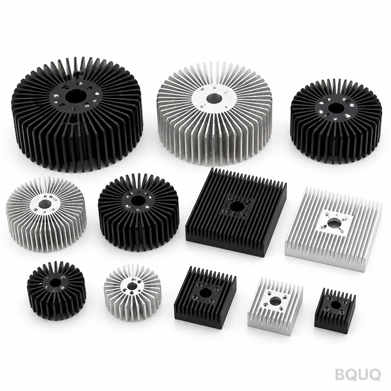
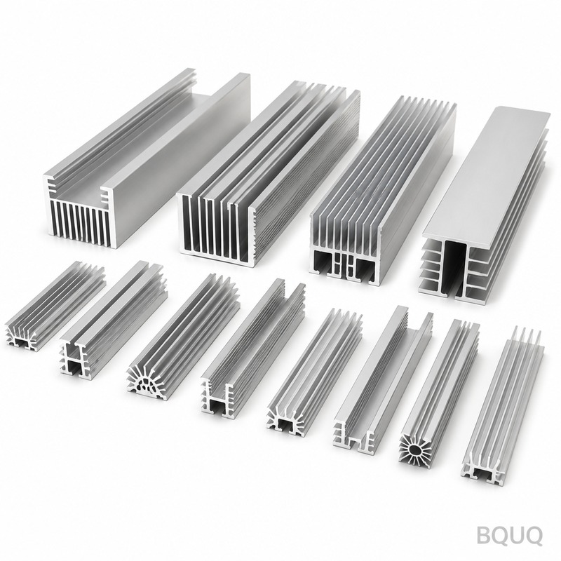
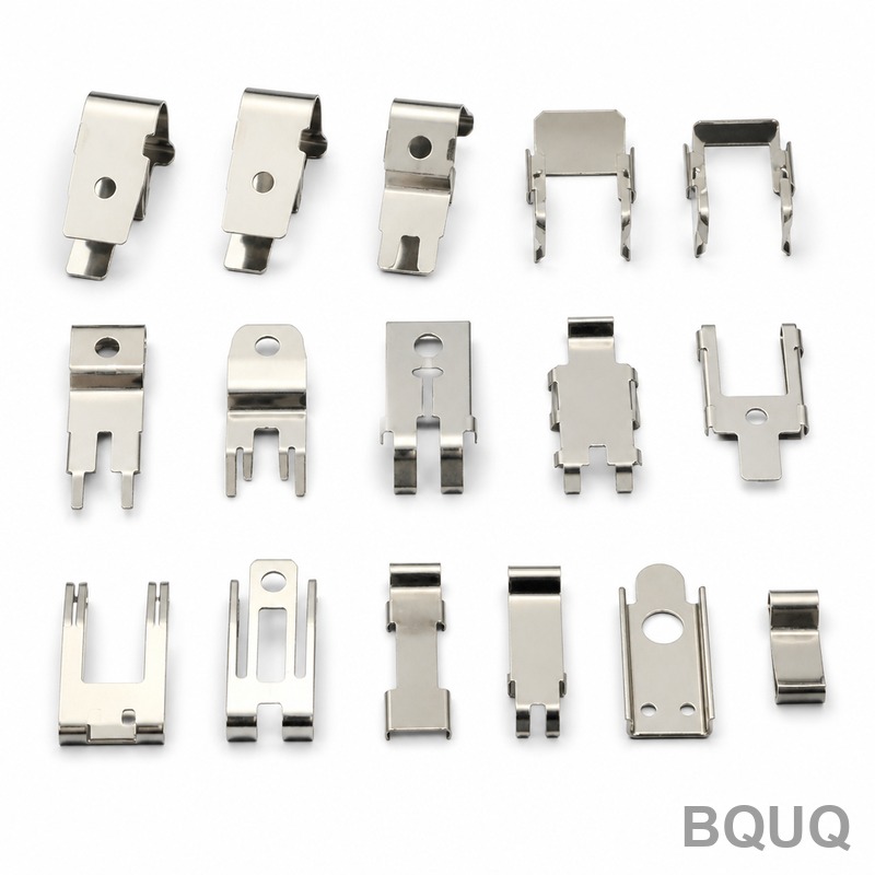
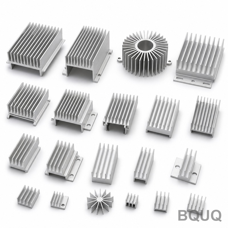
aluminum heat sink plate: ADC12 die-cast aluminium, 1.0 mm fins at 1.5 mm pitch, 0.05 mm over 100 mm flatness, 0.35 K/W thermal resistance. MOQ 50 pcs, ships...
aluminum heat sink plate
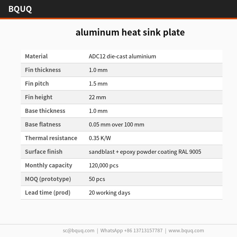
aluminum heat sink plate: ADC12 die-cast aluminium, 1.0 mm fins at 1.5 mm pitch, 0.05 mm over 100 mm flatness, 0.35 K/W thermal resistance. MOQ 50 pcs, ships...
Get a Fast Quote for This Part
Send us your drawing / quantity / material — reply within 24h.
The aluminum heat sink plate uses ADC12 die-cast aluminium with a 1.5 mm fin pitch and 1.0 mm stock, stamped in a single 63 T stroke. It holds 0.05 mm over 100 mm on the mounting face, achieves 0.35 K/W thermal resistance, and maintains ±0.05 mm pitch across a 120,000 pcs run at a 25 s cycle.
The aluminum heat sink plate combines 1.5 mm fin pitch with 1.0 mm stock in ADC12 die-cast aluminium, so 20 x 20 x 10 mm parts keep 0.05 mm over 100 mm on the mounting face. Thermal resistance is 0.35 K/W, measured at CMM 0.001 mm resolution per lot.
Design Approach and Process
Stamping gives a repeatable 1.0 mm fin profile that extrusion cannot hold: the die forms every fin in one stroke, so pitch stays within ±0.05 mm across a 120,000 pcs run.
A single 63 T stroke forms the whole aluminum heat sink plate, so part cost stops scaling with complexity. Tooling runs ±0.05 mm, and the 25 s cycle feeds a 120,000 pcs line.
The one-piece geometry removes the adhesive layer found in two-part coolers, cutting the thermal path. Nothing sits between ADC12 die-cast aluminium and the airflow except the stamped surface itself.
Stamped construction tolerates batch variation better than extrusion: die wear shows up first as a measurable shift in fin pitch, which inspection catches at CMM 0.001 mm resolution rather than in the field.
The sandblast + epoxy powder coating RAL 9005 finish is applied after forming, so corrosion protection does not get cut through at the fin roots the way it does on machined alternatives.
Material Selection and Surface Finish
The standard material is ADC12 die-cast aluminium, supplied with sandblast + epoxy powder coating RAL 9005. For applications where EV and OBC charger exposure is a concern, we recommend the passivated route; where conductivity matters more than weight, copper C110 raises thermal performance and roughly doubles unit mass.
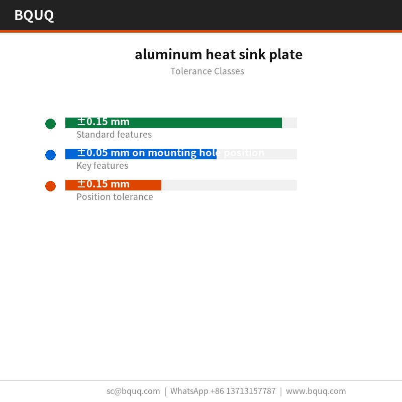
General dimensions run to ±0.15 mm, with critical features such as ±0.05 mm on mounting hole position held separately. Formed geometry inherits tooling repeatability of ±0.05 mm, and hole position is held to ±0.15 mm. Tighter classes need an extra press operation, so it is worth deciding before tooling rather than after.
Inspection Before Every Shipment
Flatness is checked on a granite surface plate, 20 °C against a 0.05 mm over 100 mm limit, and fin pitch is verified optically at ±0.05 mm. Reports go out with each lot.
Each batch carries a CMM report from CMM 0.001 mm resolution. We record flatness, pitch, base thickness and hole position, and flag anything outside ±0.15 mm before it leaves the line.
Sampling is AQL 0.65 for critical dimensions and 1.5 for general, with CMM 0.001 mm resolution on every first article. Deviations beyond ±0.15 mm trigger a full-lot sort.
Flatness is measured on granite rather than on cast iron, because 0.05 mm over 100 mm at 20 x 20 x 10 mm reads differently on a plate that has not been lapped. Records keep both readings.
Where This Part Is Used
EV and OBC charger programs are the reason this geometry exists. Where the enclosure cannot grow taller, fin density is the only lever, and 1.5 mm pitch with 1.0 mm stock is the practical ceiling for aluminium.
For EV and OBC charger builds, the 0.05 mm over 100 mm mounting face matters as much as the thermal rating: it decides whether thermal interface material spreads evenly or pools at one end.
Where a aluminum heat sink plate runs at EV and OBC charger volumes, part-to-part consistency decides field returns. ±0.05 mm on a 120,000 pcs run keeps the thermal curve inside one band.
In EV and OBC charger, the base usually doubles as the mounting interface. 1.0 mm with 0.05 mm over 100 mm flat gives a stable surface for the EV and OBC charger thermal pad.
Specifications
Parameter
Value / Range
Material
ADC12 die-cast aluminium
Fin thickness
1.0 mm
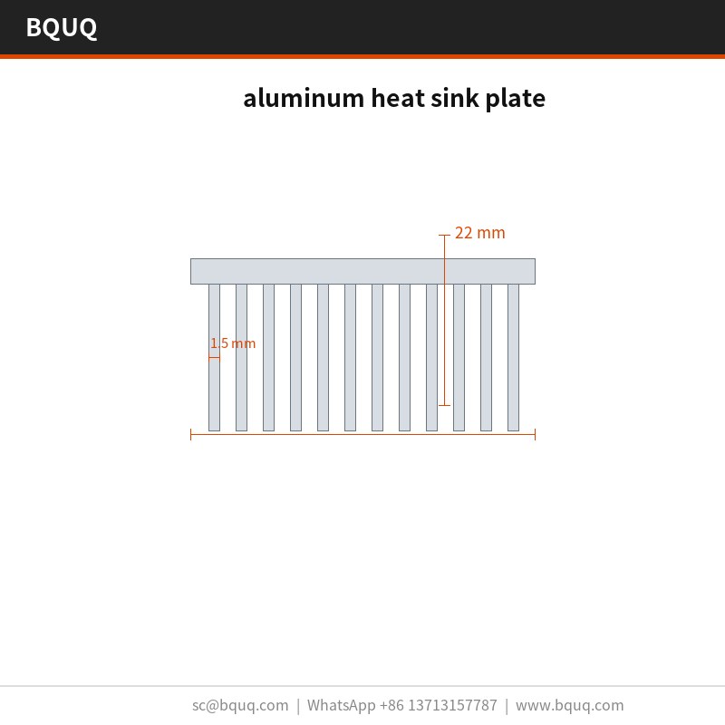
Fin pitch
1.5 mm
Fin height
22 mm
Base thickness
1.0 mm
Base flatness
0.05 mm over 100 mm
Thermal resistance
0.35 K/W
Thermal test condition
ΔT = 60 K, natural convection
Surface finish
sandblast + epoxy powder coating RAL 9005
Size range
20 x 20 x 10 mm
FAQ: Your Questions Before Ordering
Which materials do you recommend?
ADC12 die-cast aluminium is the standard choice. For EV and OBC charger in a corrosive environment we specify 6063-T5 with sandblast + epoxy powder coating RAL 9005; for the highest conductivity we move to copper C110, which raises cost and weight but drops thermal resistance by roughly half at the same envelope.
Do you make the aluminum heat sink plate in different sizes?
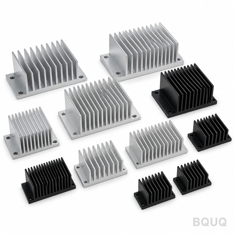
The family covers 20 x 20 x 10 mm, with unit weights from 120 g. Because the base is pressed, new sizes are a die insert change rather than a new press line, so development is usually 2 weeks rather than 8.
What are the packing and shipping conditions?
Standard packing is PE bag + honeycomb carton, 15 kg per carton. We quote EXW. Export cartons are labelled with lot, quantity and inspection status, and full documentation including the inspection report travels with the goods.
How do you prevent galvanic corrosion?
The key is avoiding a second metal at the wet contact area. We recommend sandblast + epoxy powder coating RAL 9005 and, where the part touches an aluminium chassis, an isolating washer. Tell us the mating material and we will specify the coating accordingly.
What is the difference between your aluminum heat sink plate and a skived fin aluminum heat sink plate?
Skived fins are milled, so you get thin, tall fins and higher density in a given height, but the cost scales directly with fin area. Stamping gives the same result in one stroke at a much lower unit cost below 120,000 pcs. For EV and OBC charger in a fixed-height enclosure, stamped is normally the right answer.
Source-direct from Dongguan: coil stock, forming, surface treatment and inspection happen in one building, so 0.05 mm over 100 mm flatness is verified before the part is packed.
Our EV and OBC charger experience runs back to the first tooling programme in 2015. That history is why the standard sandblast + epoxy powder coating RAL 9005 and ±0.15 mm are conservative rather than optimistic.
Production runs on 25 s cycles with in-line vision on 0.05 mm over 100 mm. That is what keeps a 120,000 pcs commitment credible in peak season.
Request a quote: sc@bquq.com | WhatsApp +86 13713157787 | Dongguan, China
±0.05 mm fin pitch; 0.05 mm over 100 mm mounting face
Lead time
Not specified in article
MOQ
Not specified in article
Capacity
120,000 pcs run; 25 s cycle
Selection / comparison
Option
Best for
Trade-off
Stamped aluminum heat sink plate
Repeatable 1.0 mm fin profile
Die wear shifts fin pitch, caught by CMM
Extruded heat sink
Simple uniform cross-sections
Cannot hold 1.0 mm fin profile as repeatably
Two-part cooler with adhesive
Complex geometries
Adhesive layer adds thermal path resistance
Sandblast + epoxy powder coating RAL 9005
Corrosion protection after forming
Applied post-forming to avoid cut-through at fin roots
Process / inspection
Stage
Control
Record
Stamping
Single 63 T stroke forms whole plate
±0.05 mm tooling run
Fin forming
Die forms every fin in one stroke
Pitch within ±0.05 mm across 120,000 pcs
Inspection
CMM 0.001 mm resolution per lot
Thermal resistance 0.35 K/W measured
Coating
Sandblast + epoxy powder coating RAL 9005 after forming
Corrosion protection not cut at fin roots
Frequently Asked Questions
What is the fin pitch and stock thickness of the aluminum heat sink plate?
The plate combines a 1.5 mm fin pitch with 1.0 mm stock in ADC12 die-cast aluminium. This allows 20 x 20 x 10 mm parts to maintain 0.05 mm over 100 mm on the mounting face.
What thermal resistance can I expect from this heat sink plate?
Thermal resistance is 0.35 K/W, measured at CMM 0.001 mm resolution per lot. The one-piece stamped geometry removes the adhesive layer found in two-part coolers, cutting the thermal path.
How repeatable is the fin profile in production?
Stamping gives a repeatable 1.0 mm fin profile that extrusion cannot hold. The die forms every fin in one stroke, so pitch stays within ±0.05 mm across a 120,000 pcs run.
What is the cycle time and production capacity?
A single 63 T stroke forms the whole aluminum heat sink plate. Tooling runs ±0.05 mm, and the 25 s cycle feeds a 120,000 pcs line.
How does stamped construction handle batch variation?
Stamped construction tolerates batch variation better than extrusion. Die wear shows up first as a measurable shift in fin pitch, which inspection catches at CMM 0.001 mm resolution rather than in the field.
The sandblast + epoxy powder coating RAL 9005 finish is applied after forming. This ensures corrosion protection does not get cut through at the fin roots the way it does on machined parts.
Why does the one-piece design improve thermal performance?
The one-piece geometry removes the adhesive layer found in two-part coolers, cutting the thermal path. Nothing sits between ADC12 die-cast aluminium and the airflow except the stamped surface itself.