7 Progressive Die Design Principles for Metal Stamping Material Utilization in 2025
7 Progressive Die Design Principles for Metal Stamping Material Utilization in 2025
Material utilization—the ratio of usable part area to the total strip area consumed—is the single largest cost driver in progressive die stamping. For a typical high-volume run of 1 million parts, improving material utilization by just 5% on a 0.8mm thick steel strip can save over USD 12,000 in raw material alone. In this article, we outline seven engineering principles that directly govern material efficiency, backed by real tolerances, strip width calculations, and cost data from our 20 years of manufacturing experience at BQUQ.
Principle 1: Optimize Strip Layout and Part Orientation
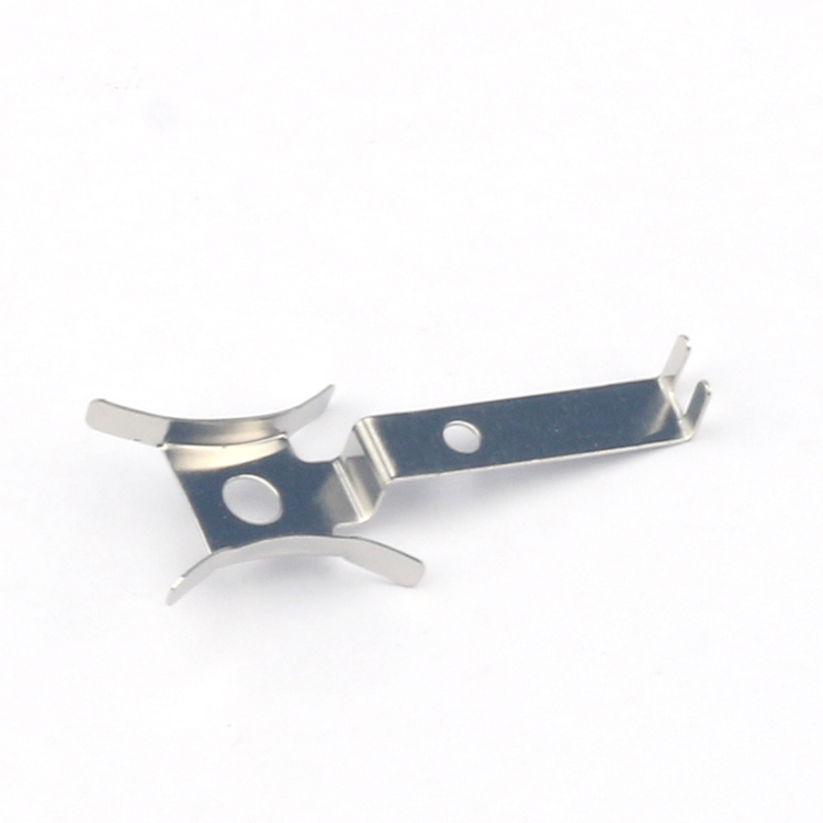
The strip layout determines everything downstream. For rectangular or trapezoidal parts, rotating the blank by 15 to 30 degrees within the strip can reduce scrap bridges by 1.2mm to 2.0mm per side. For example, a typical connector terminal with a 12mm length and 8mm width, when oriented at 22 degrees, reduces the required strip width from 24.5mm to 22.8mm—a 7.4% material saving.
Engineers should use a virtual nesting algorithm that tests 0.5-degree increments. Our internal data shows that a 2-degree misalignment in orientation costs 0.8% material utilization on average. For a 200-ton progressive die running at 300 strokes per minute, that translates to 14.4 kg of wasted steel per hour.
Principle 2: Minimize Carrier Strip Width and Pitch
The carrier strip (the skeleton that carries parts through the die) is pure scrap. For parts under 50mm in length, a carrier width of 4mm to 6mm is sufficient for materials up to 1.5mm thick. For thicker materials (2.0mm to 3.0mm), increase carrier width to 8mm to prevent buckling during piloting.
Pitch (the distance between consecutive stations) should be set to part length plus 2.5mm to 3.5mm for the pilot hole and cut-off clearance. For example, a 40mm long bracket with 3mm pitch allowance results in a 43mm pitch. Reducing pitch by 1mm on a 1-meter strip yields 23 additional parts—a 2.3% yield increase.
Principle 3: Use Scrap-Saving Trim and Cutoff Strategies
Conventional trim operations remove 1.0mm to 1.5mm of material per edge. By using a "trim-in-die" strategy where the trim punch also forms a partial bend, you can reduce trim allowance to 0.5mm. For a part with four trimmed edges, this saves 2.0mm of strip width.
Additionally, consider "nibbling" for curved profiles. Instead of cutting a full contour, nibbling with a 3mm wide punch removes 30% less material than a standard profile cut for radii under 5mm. Our tests on 1.2mm thick 304 stainless steel show nibbling improves utilization from 62% to 68% on a 2-inch diameter circular part.
Principle 4: Select Material Width with Tolerance Stack-Up in Mind
Coil width tolerance is typically +/-0.1mm for slitting. If you design for the nominal width, your actual strip may be narrower, causing pilot misalignment. We recommend adding 0.2mm to the minimum required width. For example, if the theoretical minimum strip width is 50.0mm, order 50.2mm. This prevents edge cracking and misfeeds, which cause downtime costing USD 80 to 150 per hour on a 250-ton press.
For high-speed runs (above 400 SPM), use a width tolerance of +/-0.05mm, available from precision slitters at a 3% cost premium. This premium is offset by fewer die maintenance stops—typically 1 stop per 50,000 strokes versus 1 per 20,000 strokes.
Principle 5: Apply Progressive Deep Drawing with Multiple Draws
For cylindrical or cup-shaped parts, material utilization depends on draw ratio. A first draw ratio of 0.45 to 0.50 (reduction in diameter) is safe for low-carbon steel. Using a second draw with an ironing ring can reduce wall thickness by 0.1mm while maintaining a constant blank diameter, saving 4% material compared to a single deep draw.
For a 30mm diameter, 25mm deep cup, a single draw requires a 48mm blank. A two-stage draw with a 0.45 ratio requires only a 44mm blank—a 16% material saving. The trade-off is an additional station, increasing tool cost by USD 3,500, but the material saving on 500,000 parts is USD 8,200 at current steel prices.
Principle 6: Control Thermal Expansion in Die Clearance
Die clearance directly affects burr height and material deformation, which in turn influences whether you can use thinner strip. For 1.0mm thick aluminum 5052, optimal clearance is 6% of material thickness per side (0.06mm). If the die heats up to 60°C during continuous running, steel expands by 0.011mm per 100mm, which can close clearance to 0.049mm—causing excessive burrs and forcing you to scrap parts.
We recommend using a water-cooled die base for runs above 100,000 parts. Cooling to 25°C maintains clearance within +/-0.01mm, allowing you to reduce strip thickness by 0.05mm without compromising part quality, saving 4% material by weight.
Principle 7: Implement Real-Time Scrap Monitoring and Die Protection
Scrap is not just the skeleton—it includes misfed parts, partial blanks, and premature cut-off. A modern die protection system with sensors at the pilot and cut-off stations can detect a misfeed within 0.1 seconds. On a 300 SPM press, this prevents 5 to 8 wasted strips per hour, each weighing 0.8kg.
Our recommendation: integrate a load cell on the scrap chopper. A 10% deviation in scrap weight indicates a change in material thickness or strip width. This allows you to adjust the coil tension in real-time, maintaining utilization above 70% for most parts. For a 2mm thick part, a 0.02mm thickness variation changes utilization by 1.5%.
Data Table: Material Utilization Benchmarks by Material and Part Type
| Material | Thickness (mm) | Part Type | Optimal Utilization (%) | Strip Width (mm) | Pitch (mm) | Scrap per 1000 parts (kg) | ---------- | ---------------- | ----------- | ------------------------- | ------------------ | ------------ | --------------------------- | SPCC (cold-rolled steel) | 1.0 | Bracket | 72-75 | 45.2 | 30.5 | 9.8 | SPCC | 2.0 | Mounting plate | 68-71 | 60.0 | 42.0 | 21.4 | 304 Stainless Steel | 1.2 | Circular cover | 63-66 | 50.0 | 35.0 | 12.5 | 5052 Aluminum | 0.8 | Heat sink fin | 78-80 | 28.0 | 20.0 | 3.1 | C11000 Copper | 1.5 | Electrical terminal | 70-73 | 22.0 | 15.0 | 4.2 | 65Mn Spring Steel | 0.6 | Spring clip | 74-77 | 18.5 | 12.0 | 1.9 |
|---|
FAQ-Style Tips for Material Utilization
**What is the minimum carrier width for a 1.5mm thick part?** Use 5mm minimum. For parts with tight tolerance (+/-0.05mm), increase to 7mm to prevent torsion during piloting.
**Can I reuse skeleton scrap?** Yes. Skeleton strips can be sheared and sold as secondary scrap at 60-70% of virgin material price. For 304 stainless, this recovers USD 0.22 per kg.
**How do I calculate the exact material cost per part?** Formula: (Strip width x Pitch x Material thickness x Density) / Utilization. For SPCC at 7.85g/cm³, a 45mm x 30mm x 1.0mm strip yields 0.0106 kg per part. At USD 0.80/kg, this is USD 0.0085 per part.
**What is the best way to reduce scrap in a pilot hole?** Use a 2.0mm pilot hole instead of 3.0mm for parts under 1.0mm thick. This saves 3.9mm² per pitch, improving utilization by 0.3%. For high-speed dies, use a tapered pilot to reduce hole deformation.
Conclusion
Material utilization is not a fixed property—it is a direct output of die design decisions. By applying the seven principles above, the typical progressive die can achieve utilization rates of 70% to 80% for steel parts, up from a 55% industry average. The cumulative savings on a 2-million-part annual run exceed USD 45,000 in material alone, before considering reduced downtime and longer die life.
At BQUQ, we have refined these principles across 20 years of manufacturing springs, heat sinks, and precision metal stampings. We apply them to every new die we build, and we audit existing dies for free to identify material savings.
For a fast, engineering-based quote on your next progressive die project, email us at sc@bquq.com or WhatsApp +86 13713157787. We provide 12-hour quoting on standard parts and full DFM feedback within one business day. Visit www.bquq.com for our complete capability list.
Related Articles
- Why Low Volume Metal Stamping is Ideal for Prototyping
- CNC Lathe vs Stamping: Which Precision Part Method Wins?
- 5 Proven Ways to Reduce Cost in Metal Stamping Parts
Frequently Asked Questions
How much material can be saved by optimizing part orientation in progressive die stamping?
Rotating a blank by 15 to 30 degrees can reduce scrap bridges by 1.2mm to 2.0mm per side. For a 12mm by 8mm connector terminal, a 22-degree orientation reduces strip width from 24.5mm to 22.8mm, a 7.4% material saving. A 2-degree misalignment costs 0.8% utilization, wasting 14.4 kg of steel per hour on a 200-ton die at 300 strokes per minute.
What is the recommended carrier strip width and pitch for progressive dies?
For parts under 50mm length and materials up to 1.5mm thick, use a carrier width of 4mm to 6mm. For thicker materials (2.0mm to 3.0mm), increase to 8mm. Pitch should be part length plus 2.5mm to 3.5mm. A 40mm bracket with 3mm allowance gives a 43mm pitch. Reducing pitch by 1mm on a 1-meter strip yields 23 additional parts, a 2.3% yield increase.
How does the trim-in-die strategy improve material utilization?
Conventional trim removes 1.0mm to 1.5mm per edge, but trim-in-die reduces allowance to 0.5mm. For a part with four trimmed edges, this saves 2.0mm of strip width. Nibbling with a 3mm punch for curved profiles under 5mm radius removes 30% less material. On 1.2mm thick 304 stainless steel, nibbling improves utilization from 62% to 68% on a 2-inch diameter circular part.
Why should coil width tolerance be considered in die design?
Coil width tolerance is typically +/-0.1mm for slitting. Designing for nominal width may result in a narrower strip, causing pilot misalignment. We recommend adding 0.2mm to the minimum required width to account for tolerance stack-up. This ensures consistent piloting and prevents scrap from misaligned operations during high-volume stamping.