Burr in Metal Stamping: Causes, Tolerances, and 7 Control Methods
Burr in Metal Stamping: Causes, Tolerances, and 7 Control Methods
**Direct Answer:** A burr in metal stamping is an undesirable raised edge or small, sharp protrusion of material formed on the workpiece edge when the punch and die clearance is incorrect, or when tooling wears beyond specification. Burr control is achieved primarily through precise die clearance management (typically 5-12% of material thickness per side), regular tooling maintenance schedules, and secondary finishing operations like tumbling or vibratory deburring when tolerances below 0.05 mm are required.
---
H2: Understanding Burr Formation in the Stamping Process
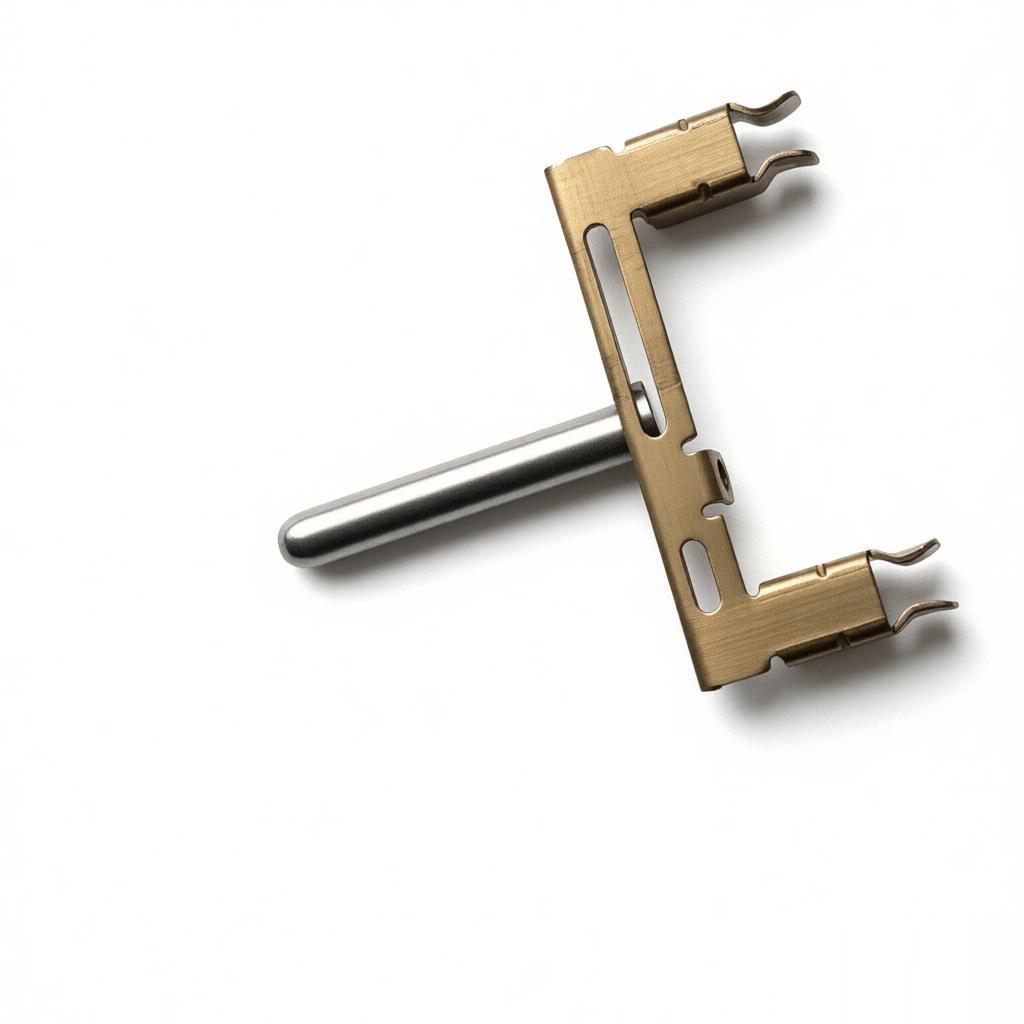
In precision metal stamping, burrs are not a defect of material but a predictable result of fracture mechanics. When a punch forces material through a die, the sheet metal undergoes four distinct zones: rollover, burnish, fracture, and burr. The burr forms in the last zone when the punch pushes the material past the die edge without cleanly shearing it. This occurs because the clearance between the punch and die is too large, allowing the material to bend and stretch before fracture, leaving a ragged lip on the bottom edge of the part.
At BQUQ’s Dongguan facility, we measure burr height using a digital micrometer with a 0.001 mm resolution. For standard carbon steel (SPCC, DC01), an acceptable burr height for functional parts is below 0.05 mm. For critical applications, such as automotive battery terminals or medical device components, we target 0.02 mm or less. The physics are simple: the ratio of clearance to material thickness determines the fracture angle. For a 1.0 mm thick cold-rolled steel sheet, the optimal per-side clearance is 0.05–0.08 mm (5–8%). If clearance exceeds 0.12 mm, burr height will typically exceed 0.10 mm, requiring secondary deburring.

---
H2: Root Causes of Burr Defects: Tooling, Clearance, and Material Variables
Three primary variables control burr formation: die clearance, tool sharpness, and material properties.
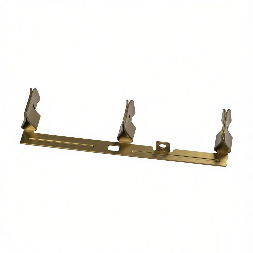
**1. Die Clearance (Per Side):** Incorrect clearance is the most common cause. Too much clearance creates a large burr and a heavier rollover. Too little clearance causes secondary shearing and a thin, sharp burr that can break off during handling. Our engineering standard uses the following formula for initial setup: Clearance (per side) = Material Thickness × 4% to 8% for soft materials (aluminum 5052, brass), and 8% to 12% for hard materials (stainless steel 301, spring steel).
**2. Tool Wear:** A punch with a cutting edge radius greater than 0.02 mm will start to push material rather than cut it. We recommend a tool inspection interval of 50,000 strokes for stainless steel and 100,000 strokes for mild steel. At these intervals, we measure the cutting edge radius with an optical comparator. When the radius exceeds 0.03 mm, the punch is re-ground. The cost of re-grinding a typical progressive die punch is USD 15–40 per punch, versus the cost of scrapping a batch of 10,000 parts due to burr rejection, which can exceed USD 500.
**3. Material Hardness Variation:** If the incoming coil hardness varies by more than ±10 HV (Vickers hardness), burr size will fluctuate. For example, a batch of SPCC steel with hardness ranging from 90 HV to 110 HV will produce inconsistent fracture points. We require material certificates (MTC) with hardness data for every coil and perform a Rockwell B spot-check on the first 10 pieces of every new coil.
---
H2: Quantitative Tolerance Standards for Burr Height
Industry standards provide clear numerical limits. The most referenced is the Chinese National Standard GB/T 13914-2002 (for stamping parts tolerances) and the automotive standard Q/CAF 01.0001 (for burr height). Below is a comparative table for common materials and thicknesses, based on our production data over the last 24 months.
| Material | Thickness (mm) | Per-Side Clearance (%) | Max Burr Height – Standard (mm) | Max Burr Height – Precision (mm) | Recommended Deburring Method | Typical Cost per 1000 Parts (CNY/USD) | --------------------- | ---------------- | ------------------------ | -------------------------------- | ---------------------------------- | ------------------------------ | --------------------------------------- | SPCC (mild steel) | 1.0 | 5–8% | 0.08 | 0.03 | Tumbling (ceramic media) | 15 CNY / USD 2.10 | SPCC (mild steel) | 2.0 | 6–9% | 0.12 | 0.05 | Vibratory bowl | 25 CNY / USD 3.50 | SUS 304 (stainless) | 1.5 | 8–12% | 0.10 | 0.04 | Manual deburring (file) | 60 CNY / USD 8.40 | AL 5052 (aluminum) | 2.5 | 4–6% | 0.15 | 0.06 | Dry ice blasting | 40 CNY / USD 5.60 | C17200 (beryllium copper) | 0.8 | 5–7% | 0.05 | 0.02 | Electrolytic polishing | 80 CNY / USD 11.20 |
|---|
*Note: Precision burr height is achievable only with a dedicated fine-blanking die or a secondary trimming operation. Standard progressive die stamping cannot consistently hold below 0.03 mm on materials over 1.5 mm thick.*
---
H2: Seven Practical Burr Control Methods for High-Volume Production
Based on 20 years of running 80+ stamping presses at our Dongguan plant, here are the control methods ranked by cost-effectiveness:
**Method 1: Optimize Die Clearance at Design Stage (Zero Cost)** During tool design, we simulate clearance using CAD software (AutoForm). For a new part, we order test strips of the exact material grade and thickness. We run a 50-piece trial with three different clearances: low, nominal, and high. We measure burr height on every piece and select the clearance that yields the minimum average burr without excessive rollover (rollover depth should not exceed 15% of material thickness).
**Method 2: Implement a Tooling Wear Monitoring System (Low Cost)** We install a load cell on the press ram. When the stamping force drops by 8% from the baseline (indicating a dull punch), the press automatically stops. This prevents the production of thousands of burred parts. The load cell retrofit costs approximately USD 2,500 per press, and the payback period is under 4 months for a 24/7 operation.
**Method 3: Use a Burr-Free (Fine Blanking) Process for Critical Edges** For parts requiring burr height below 0.02 mm, we recommend fine blanking. This process uses a V-ring indenter and a counter-punch to create a smooth shear surface. The tooling cost is 30–50% higher than conventional stamping, but it eliminates secondary deburring entirely. Lead time for a fine blanking die is 6–8 weeks versus 3–4 weeks for a standard die.
**Method 4: Secondary Vibratory Deburring (Most Common)** For standard parts, we use a vibratory bowl with ceramic media (triangular shape, 5 mm size). The process runs for 30–45 minutes per batch of 5,000 parts. It removes burrs up to 0.10 mm and rounds sharp edges to a radius of 0.05–0.10 mm. The cost is low (USD 2–5 per 1,000 parts), but it cannot remove burrs larger than 0.15 mm effectively. It also adds a slight matte finish to the surface, which may require a subsequent brightening step for cosmetic parts.
**Method 5: Thermal or Electrochemical Deburring (High Precision)** For internal cross-holes or complex geometries, thermal energy deburring (TED) uses a combustible gas mixture to burn off burrs in a sealed chamber. The process takes 20 milliseconds per cycle and removes burrs uniformly without affecting dimensions. Cost per part is higher (USD 0.02–0.05 per piece), but it is the only method for internal burrs. Electrochemical deburring (ECD) is used for softer metals like aluminum, with a cycle time of 15 seconds and a burr removal accuracy of ±0.005 mm.
**Method 6: Edge Coining (In-Die Deburring)** In progressive dies, we add a coining station that presses the burr flat against the part surface. This is effective for burrs less than 0.05 mm. The coining punch applies a force of 3–5 tons per square centimeter, which compresses the burr into the material. This method adds no cycle time and no extra cost, but it increases tool wear by 15%.
**Method 7: Real-Time Optical Inspection (Quality Assurance)** We use inline vision systems with a 5-megapixel camera and a telecentric lens. The system detects burr height greater than 0.05 mm at a speed of 120 parts per minute. The rejection accuracy is 99.7%. The system costs USD 18,000 to integrate, but it reduces customer returns from 2% to 0.1%.
---
H2: FAQ-Style Tips for Engineers and Purchasing Managers
**Q: What burr height is acceptable for a part that will be nickel-plated?** A: For electroplating, the burr must be below 0.03 mm. Any larger burr will cause plating buildup at the edge, leading to poor adhesion and flaking. We recommend a two-step process: stamping with tight clearance (5%) followed by vibratory deburring, then plating.
**Q: How does burr affect the fatigue life of a stamped spring?** A: A burr acts as a stress riser. In a spring steel part (e.g., 65Mn, 0.8 mm thick), a burr of 0.10 mm reduces fatigue life by 40% compared to a burr-free edge. We test this using a fatigue tester at 10 Hz with a stress amplitude of 600 MPa. The difference between a 0.02 mm burr and a 0.10 mm burr is 1.2 million cycles versus 700,000 cycles to failure.
**Q: Can we deburr after heat treatment?** A: No, deburring after heat treatment is difficult because the increased hardness (HRC 40–50) wears out the ceramic media quickly. We always deburr before heat treatment. The only exception is for parts requiring a very sharp edge, which we then polish with a diamond paste after tempering.
**Q: What is the price difference between standard and precision burr control?** A: For a typical 1.5 mm thick stainless steel part, standard burr control (0.10 mm) adds no extra cost if the die is designed correctly. Precision burr control (0.03 mm) adds USD 12–18 per 1,000 parts due to additional tooling maintenance (more frequent re-grinding) and a slower press speed (reduced from 80 SPM to 60 SPM). For fine blanking, add USD 25–40 per 1,000 parts.
**Q: How do you inspect burr on a curved or irregular edge?** A: We use a profilometer with a stylus tip radius of 2 micrometers. The stylus traces the edge profile, and the software calculates the maximum peak height. For curved edges, we use a 3D optical scanner with a resolution of 0.01 mm. The inspection time is 30 seconds per part.
---
H2: Practical Recommendations for Your Next Stamping Project
When you send us a drawing, we will review the burr requirements against the material grade and thickness. Our engineering recommendation is simple: do not specify a burr tolerance tighter than necessary. A tolerance of 0.10 mm is achievable with standard tooling at no extra cost. A tolerance of 0.05 mm requires a tooling maintenance interval of 30,000 strokes instead of 100,000, which increases tool cost by approximately 8%. A tolerance of 0.02 mm requires fine blanking or a secondary grinding operation, which will increase part cost by 20–35%.
For high-volume parts (over 500,000 pieces per year), we recommend investing in a dedicated deburring line (vibratory bowl + drying oven) at a capital cost of USD 8,000–12,000. This line will process 5,000 parts per hour and reduce per-part deburring cost to less than USD 0.001. For low-volume prototype parts, we recommend manual deburring with a carbide scraper, which costs USD 2 per part but is fully adequate for validation samples.
We also advise you to include a burr direction note on your drawing. Burr direction is controlled by the die design: if the punch enters from the top, the burr is on the bottom edge. Specify "burr up" or "burr down" to align with your assembly requirements. A burr facing the wrong direction can cause short circuits in electrical connectors or interfere with mating parts.
---
Conclusion: Burr Control Is a Design and Process Discipline
Burr in metal stamping is not an unavoidable defect; it is a measurable, controllable output of the shearing process. By specifying a realistic burr height based on the data table above, selecting the correct die clearance, and implementing a scheduled tooling maintenance plan, you can achieve burr-free functional edges at a minimal cost increase. The key is to involve the manufacturer early in the design phase. At BQUQ, we have 20 years of experience in CNC machining, metal stamping, springs, and heat sinks. We will review your drawing, identify the critical burr edges, and propose the most economical control method before we cut any steel.
We provide free DFM (Design for Manufacturing) feedback within 12 hours of receiving your inquiry. If you have a stamped part with a burr issue, or a new design that requires tight burr control, send us your 2D or 3D file. We will respond with a feasibility analysis, a specific die design recommendation, and a firm quote.
**Contact BQUQ for an immediate evaluation:** - Email: sc@bquq.com - WhatsApp: +86 13713157787 - Website: www.bquq.com
We are ready to help you eliminate burr problems and lower your total cost of ownership.
Related Articles
- Design for Stamping: 7 Blanking Layout Rules to Cut Scrap Cost by 18% in 2025
- Why Low Volume Metal Stamping is Ideal for Prototyping
- 5 Proven Ways to Reduce Cost in Metal Stamping Parts
Frequently Asked Questions
What is the acceptable burr height for standard carbon steel parts?
For standard carbon steel (SPCC, DC01), an acceptable burr height for functional parts is below 0.05 mm. For critical applications like automotive battery terminals or medical device components, we target 0.02 mm or less, measured with a digital micrometer with 0.001 mm resolution.
What causes burrs in metal stamping and how can they be controlled?
Burrs form when punch and die clearance is incorrect or tooling wears beyond specification. Control is achieved through precise die clearance management (typically 5-12% of material thickness per side), regular tooling maintenance, and secondary finishing like tumbling or vibratory deburring when tolerances below 0.05 mm are required.
What is the recommended die clearance for different materials?
For soft materials like aluminum 5052 or brass, clearance per side is 4% to 8% of material thickness. For hard materials like stainless steel 301 or spring steel, it is 8% to 12%. For a 1.0 mm cold-rolled steel sheet, optimal per-side clearance is 0.05–0.08 mm (5–8%).
How often should stamping tools be inspected to prevent burrs?
We recommend tool inspection every 50,000 strokes for stainless steel and 100,000 strokes for mild steel. At these intervals, we measure the cutting edge radius with an optical comparator. When the radius exceeds 0.03 mm, the punch is re-ground, as a radius greater than 0.02 mm starts pushing material rather than cutting.