
Compound Die Stamping: Definition, Tolerances, and When to Use It
A compound die is a stamping tool that performs multiple operations, typically blanking and piercing, in a single press stroke within one station. You should use a compound die when your part requires high flatness, precise hole-to-edge relationships, and production volumes between 10,000 and 1,000,000 pieces, where the cost of a progressive die cannot be justified.
Fundamental Principle of Compound Die Operation
In a compound die, the die plate contains both the blanking punch and the piercing punch. The strip is fed into the die, and during one downward stroke of the press, the blank is cut from the strip while the internal holes are pierced simultaneously. The critical difference from a progressive die is that all cutting actions occur in a single station and a single stroke, without moving the strip between operations.
The material is held flat by a stripper plate throughout the entire operation. This design ensures the blank remains perfectly flat because the cutting forces are balanced from both directions. For parts with thickness ranging from 0.1 mm to 6.0 mm, a compound die maintains flatness within 0.02 mm per 50 mm of length, which is superior to progressive stamping where strip movement can induce bending.
The die components include the upper die shoe, lower die shoe, blanking punch, piercing punch, die button, stripper plate, and pilot pins. The cutting clearance typically ranges from 4% to 8% of material thickness per side for mild steel, and 6% to 10% for stainless steel. For 1.5 mm thick SPCC steel, the recommended clearance is 0.06 mm to 0.12 mm per side.
Critical Comparison: Compound Die vs Progressive Die vs Line Die
Choosing between die types requires analyzing part geometry, tolerance requirements, and production volume. The table below presents direct engineering comparisons based on BQUQ production data from 2004 to 2025.
| Parameter | Compound Die | Progressive Die | Line Die |
| Tolerance (hole to edge) | ±0.01 mm | ±0.05 mm | ±0.10 mm |
| Flatness achieved | 0.02 mm per 50 mm | 0.05 mm per 50 mm | 0.10 mm per 50 mm |
| Production speed | 40-80 strokes/min | 200-600 strokes/min | 20-40 strokes/min |
| Tooling cost (USD) | 3,000-15,000 | 8,000-40,000 | 1,500-6,000 |
| Lead time (weeks) | 3-5 | 6-10 | 2-4 |
| Suitable volume | 10k-1M pieces | 100k-10M pieces | 1k-100k pieces |
| Material utilization | 45-60% | 60-75% | 40-55% |
| Part size limit | 200 mm x 200 mm | 300 mm x 300 mm | 500 mm x 500 mm |
The compound die offers the best tolerance-to-cost ratio for medium volumes. Its primary limitation is part size, because the blanking punch must be mounted inside the piercing punch. This nested arrangement restricts the maximum part size to roughly 200 mm by 200 mm. For larger parts, the die becomes too heavy and the press tonnage requirement increases exponentially.
Material Selection and Die Life Data
Material choice directly affects die life and achievable tolerances. For production runs exceeding 100,000 pieces, tool steel selection becomes critical. BQUQ uses the following materials for compound die components:
For blanking punches, we use D2 tool steel hardened to 58-62 HRC with a TiCN coating. This combination yields 500,000 to 800,000 strokes between regrinds for mild steel up to 2.0 mm thick. For piercing punches below 3.0 mm diameter, we specify M2 high-speed steel at 62-64 HRC to resist buckling.
The die button material depends on the workpiece material. For aluminum alloys (5052, 6061), we use A2 tool steel at 56-58 HRC. For stainless steel (304, 316), we use carbide inserts with a hardness of 88-92 HRA. Carbide die buttons extend die life by 5 to 10 times compared to D2 steel but increase tooling cost by 30-40%.
Stripper springs are critical for consistent performance. We use nitrogen gas springs rated at 150,000 cycles minimum. The stripping force must be 10-15% of the cutting force to ensure reliable part ejection. For a 50 mm diameter blank in 2.0 mm thick SPCC, the cutting force is approximately 45 tons, requiring 5-7 tons of stripping force.
Real-World Application Examples and Tolerance Data
Compound dies excel in producing parts with tight concentricity requirements. A typical application is a motor lamination for small DC motors. These parts require an outer diameter tolerance of ±0.01 mm and a center hole tolerance of ±0.005 mm, with concentricity below 0.015 mm. A compound die achieves this reliably because the blank and hole are cut simultaneously from a stationary strip.
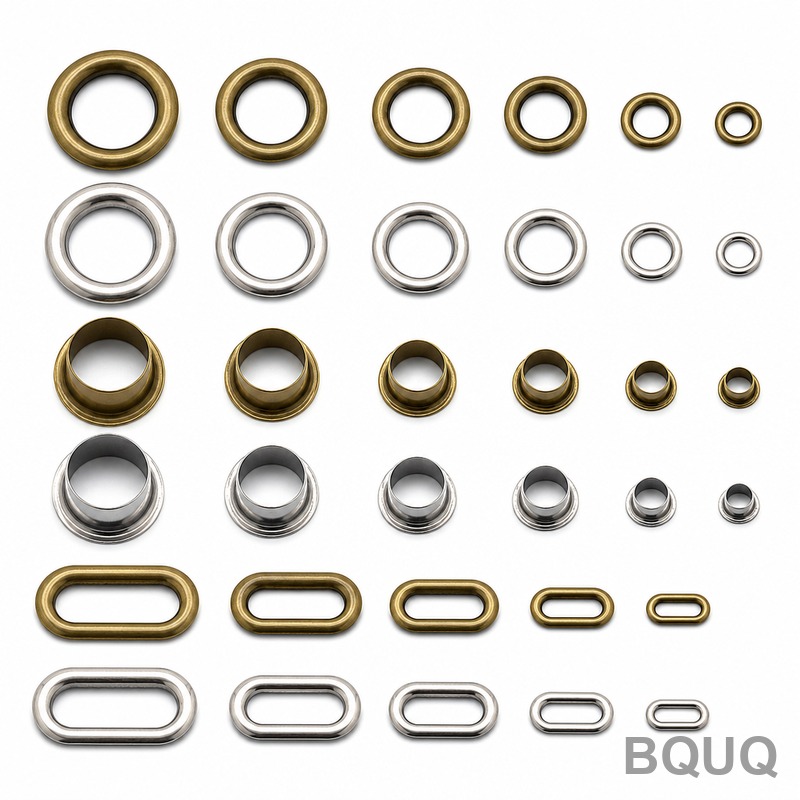
Another common application is washer production. For a flat washer with an outer diameter of 20.0 mm and an inner diameter of 8.2 mm, a compound die produces 60 pieces per minute with burr height below 0.03 mm. The burr direction is consistently on the same side, which simplifies downstream deburring if required.
Heat sink production uses compound dies for the base plate blanking operation. For an 80 mm by 80 mm heat sink base in 3.0 mm thick aluminum 6061-T6, the compound die achieves a flatness of 0.05 mm across the entire surface. This flatness is essential for thermal interface material application and subsequent machining operations.
The maximum temperature during stamping is a critical parameter. For high-speed stamping above 60 strokes per minute, the die surface temperature can reach 120-150°C. This temperature affects lubricant performance and can cause galling on aluminum parts. We recommend a chlorinated paraffin-based lubricant for steel and a low-viscosity mineral oil for aluminum to maintain die temperatures below 100°C.
Cost Analysis and Break-Even Calculation
The decision to use a compound die versus a progressive die depends on the break-even volume. For a typical part with 4 holes and a simple outline, the cost calculations are as follows:
Compound die tooling cost: 8,000 USD. Piece price at 100,000 parts: 0.35 USD per part. Progressive die tooling cost: 22,000 USD. Piece price at 100,000 parts: 0.28 USD per part. The difference in tooling cost is 14,000 USD. The per-piece savings is 0.07 USD. Break-even volume equals 14,000 divided by 0.07, which is 200,000 parts.
Below 200,000 parts, the compound die is more economical. Above 200,000 parts, the progressive die becomes cost-effective. However, this calculation assumes the part geometry is compatible with both die types. If the part requires a flatness tolerance below 0.03 mm or hole-to-edge tolerance below ±0.02 mm, the compound die is the only viable option regardless of volume.
Secondary operations add to compound die costs. If the part requires tapping, countersinking, or bending, these operations must be performed separately. Each secondary operation adds 0.05-0.15 USD per part and increases lead time by 2-5 days. A progressive die can integrate these operations at lower per-piece cost but at significantly higher tooling cost.
Practical Recommendations for Die Selection
For parts with a maximum dimension below 150 mm and thickness from 0.5 mm to 4.0 mm, choose a compound die when flatness is critical. The simultaneous cutting action eliminates the strip-bending forces that cause distortion in progressive dies.
For parts requiring hole-to-edge tolerances below ±0.02 mm, always use a compound die. The stationary strip during cutting ensures the hole position is determined only by the die geometry, not by strip feeding accuracy. Progressive dies have inherent feeding errors of ±0.03 mm to ±0.05 mm depending on the pitch and pilot system.
For production volumes below 10,000 parts, consider a wire-cut line die instead. The tooling cost savings of 50-60% outweigh the lower production speed. At volumes above 1,000,000 parts, evaluate a progressive die or a transfer die. The compound die's single-station design limits speed and creates a bottleneck in high-volume production.
When designing parts for compound die stamping, maintain a minimum web thickness of 2 times material thickness between holes and edges. For 1.0 mm thick steel, the minimum distance is 2.0 mm. Below this value, the punch may fracture or the blank may tear. Also, specify burr direction on the drawing. Compound dies produce burrs on the punch side, which is typically the bottom side of the part.
Conclusion and Engineering Summary
A compound die is the optimal choice for medium-volume production of flat parts requiring tight tolerances and high flatness. The single-stroke operation provides superior dimensional accuracy compared to progressive dies, with tooling costs 40-60% lower. The primary trade-offs are reduced production speed and a maximum part size of approximately 200 mm by 200 mm. For volumes between 10,000 and 1,000,000 parts with thickness from 0.1 mm to 6.0 mm, the compound die delivers the best combination of accuracy, cost, and lead time. BQUQ has manufactured over 5,000 compound dies since 2004, serving clients in automotive, electronics, and appliance industries. For your specific part geometry, we recommend submitting a drawing for a feasibility analysis. Our engineering team provides a detailed quote within 12 hours, including die cost, piece price, and delivery schedule. Contact us at sc@bquq.com or WhatsApp +86 13713157787. Visit www.bquq.com for more case studies and technical resources.
Related Articles
- Springback Compensation in Metal Stamping: Design & Simulation Guide
- Intelligent online inspection and closed-loop quality control: creating a zero-defect production line for stamped parts
- High-speed precision stamping and in-die microforming technology: from electronic connections to micromotor cores
Frequently Asked Questions
What is a compound die and when should I use it?
A compound die performs multiple operations, like blanking and piercing, in a single press stroke within one station. You should use it when your part requires high flatness, precise hole-to-edge relationships, and production volumes between 10,000 and 1,000,000 pieces, where a progressive die's cost cannot be justified.
What tolerances and flatness can a compound die achieve?
A compound die achieves hole-to-edge tolerance of ±0.01 mm, which is tighter than progressive dies (±0.05 mm) or line dies (±0.10 mm). For parts 0.1 mm to 6.0 mm thick, it maintains flatness within 0.02 mm per 50 mm of length, superior to progressive stamping where strip movement can induce bending.
What is the maximum part size for compound die stamping?
The maximum part size is roughly 200 mm by 200 mm. This limitation exists because the blanking punch must be mounted inside the piercing punch, and for larger parts, the die becomes too heavy and press tonnage requirements increase exponentially.
What cutting clearance should I use for 1.5 mm SPCC steel?
For 1.5 mm thick SPCC steel, the recommended cutting clearance is 0.06 mm to 0.12 mm per side. General clearance ranges from 4% to 8% of material thickness per side for mild steel, and 6% to 10% for stainless steel.


