
Compression vs Torsion vs Extension Springs: Key Differences for Engineers
Direct Answer: What Is the Difference?
Compression springs are designed to resist axial compressive forces and shorten under load, torsion springs resist rotational or twisting forces, and extension springs resist axial tensile forces and lengthen under load. The fundamental distinction lies in load direction: compression springs push back, extension springs pull back, and torsion springs twist back. Each type has distinct end configurations, stress profiles, and manufacturing tolerances that determine their application in CNC machined assemblies, metal stamping dies, and precision mechanical systems.
Mechanical Principle and Load Direction
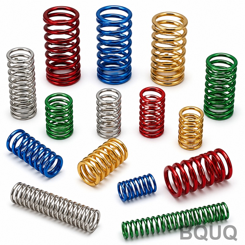
The engineering distinction begins with how each spring stores energy. A compression spring, typically wound with a constant pitch, stores energy when axially compressed. Its coils are spaced to allow deflection without coil binding. The spring rate (k) is calculated as k = Gd^4 / (8D^3N), where G is shear modulus, d is wire diameter, D is mean coil diameter, and N is active coils. For extension springs, the same formula applies but the spring is loaded in tension. The critical difference is that extension springs often have initial tension—a force required to begin separating the coils. This initial tension typically ranges from 5% to 15% of the maximum working load, depending on the spring index (D/d ratio).
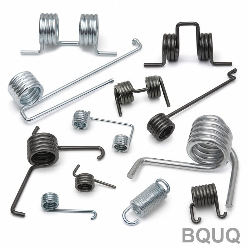
Torsion springs operate on a completely different principle. They are loaded in bending, not torsion, despite their name. The wire experiences bending stress as the legs rotate around the spring axis. The spring rate for torsion springs is calculated as k = Ed^4 / (10.8 D N), where E is Young's modulus. Torsion springs are wound with a gap between coils to accommodate the reduction in coil diameter during deflection. This gap, known as the "wind," must be calculated precisely—typically 0.5 mm to 2 mm for most industrial applications—to prevent coil binding at maximum deflection.
End Configurations and Mounting Methods
End design is where the three spring types diverge most significantly in manufacturing. Compression springs have four standard end types: closed and ground, closed not ground, open, and open and ground. For precision applications in CNC machining fixtures, closed and ground ends are mandatory. This end type provides a flat seating surface perpendicular to the spring axis within 2 degrees, ensuring uniform load distribution. The ground surface must achieve a surface finish of Ra 1.6 micrometers or better to prevent stress concentrations.
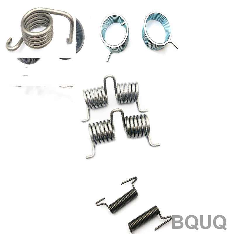
Extension springs use hooks or loops for attachment. The three common configurations are full loops, half loops, and extended hooks. Full loops have an inside diameter equal to the spring body, while extended hooks have a smaller diameter. The critical stress point in extension springs is always at the hook bend radius. For long-life applications, the hook radius must be at least 1.5 times the wire diameter. A hook radius below this threshold will cause premature fatigue failure, typically at 10,000 to 50,000 cycles versus 1,000,000 cycles for properly designed hooks.
Torsion springs have legs that transmit torque. Leg configurations include straight torsion, short hook ends, and hinged ends. The legs can be bent at various angles, typically 30 to 180 degrees, depending on the application. For precise angular positioning in mechanisms, the leg length must be held to a tolerance of plus or minus 0.5 mm. The angle between legs at free position is a critical dimension, held to plus or minus 2 degrees for most industrial springs.
Material Selection and Performance Data
Material choice significantly impacts performance across all three spring types. Music wire (ASTM A228) is the most common for compression and extension springs due to its high tensile strength, ranging from 2,000 to 2,500 MPa for wire diameters of 0.5 to 3 mm. Stainless steel 302 (ASTM A313) offers corrosion resistance but has 15% lower tensile strength. For torsion springs operating at elevated temperatures, oil-tempered chrome silicon (ASTM A401) maintains its modulus up to 250 degrees Celsius, whereas music wire degrades above 120 degrees Celsius.
| Property | Compression Spring | Extension Spring | Torsion Spring |
| Primary Load | Axial compression | Axial tension | Rotational torque |
| Common Material | Music wire ASTM A228 | Stainless 302 ASTM A313 | Chrome silicon ASTM A401 |
| Wire Diameter Range (mm) | 0.1 - 12.0 | 0.2 - 8.0 | 0.3 - 10.0 |
| Typical Tolerance (wire dia.) | plus or minus 0.01 mm | plus or minus 0.01 mm | plus or minus 0.01 mm |
| Max Working Temperature | 120 degrees C (music wire) | 200 degrees C (302 SS) | 250 degrees C (chrome silicon) |
| Typical Spring Rate Tolerance | plus or minus 5% | plus or minus 5% | plus or minus 7% |
| Relative Cost per Unit | 1.0x (baseline) | 1.3x (hooks add labor) | 1.5x (leg bending complexity) |
| Standard Lead Time (days) | 7 - 10 | 10 - 14 | 10 - 14 |
Manufacturing Tolerances and Precision Control
Precision manufacturing requires strict tolerance control across all spring dimensions. For compression springs in critical applications, the free length tolerance is plus or minus 1% or 0.5 mm, whichever is greater. The solid height—the length when coils are fully compressed—must be controlled to plus or minus 0.25 mm to prevent over-compression. The outside diameter tolerance is typically plus or minus 0.15 mm for diameters under 25 mm. At BQUQ, we use CNC coiling machines with servo-controlled pitch adjustment, achieving a pitch tolerance of plus or minus 0.05 mm on springs up to 300 mm in length.
Extension springs require additional control on initial tension. The standard tolerance is plus or minus 10% of the specified initial tension value. For example, a spring specified with 5 N initial tension must measure between 4.5 N and 5.5 N. This is verified using a tensile testing machine with a preload of 0.5 N and a testing speed of 10 mm per minute, per ASTM A125. The hook alignment is another critical dimension—the angle between the two hooks must be within plus or minus 3 degrees to prevent side loading.
Torsion springs present unique manufacturing challenges. The angular relationship between legs at free state is held to plus or minus 2 degrees. The torque tolerance is plus or minus 7% at a specified deflection angle. For high-precision applications, such as return mechanisms in CNC tool changers, we can achieve plus or minus 4% torque tolerance through 100% testing. The coil diameter of torsion springs decreases under load by approximately 0.5% to 1% of the mean diameter, which must be accounted for in the assembly design to prevent interference with adjacent components.
Fatigue Life and Testing Standards
Fatigue life varies dramatically based on spring type and operating stress. Compression springs designed for infinite life (10 million cycles) should operate at stress levels below 30% of the material's tensile strength. At 45% of tensile strength, fatigue life drops to approximately 100,000 cycles. Extension springs face additional stress at the hook, which typically limits fatigue life to 50% of an equivalent compression spring. Torsion springs loaded in bending show better fatigue characteristics, sustaining 1 million cycles at 60% of tensile strength when properly designed.
Testing protocols differ by spring type. Compression springs undergo load testing at 20%, 50%, and 100% of rated deflection, with load tolerances of plus or minus 5% at each point. Extension springs are tested for initial tension, rate, and maximum extended length. Torsion springs are tested for torque at 30%, 60%, and 100% of rated angular deflection. All three types require a proof load test to 110% of maximum working load to verify no permanent set occurs. For high-reliability applications, BQUQ performs 100% dimensional inspection using optical comparators and CNC coordinate measuring machines, with an accuracy of plus or minus 0.005 mm.
Practical Recommendations for Design Engineers
Choose compression springs when space allows axial deflection and you need predictable, linear force. They are the most cost-effective and easiest to install. Select extension springs when you need to maintain tension between two components, but be aware of the hook stress limitation—consider using a compression spring in a tube if the application has space. Choose torsion springs for rotational return mechanisms, door hinges, or counterbalance systems. For torsion springs, always specify the direction of winding (right or left) and the leg positions relative to the coil.
For all spring types, specify the operating temperature range. Above 150 degrees Celsius, music wire loses 10% of its strength and should be replaced with chrome silicon or stainless steel. For corrosive environments, 302 stainless steel is suitable for mild exposure, but 316 stainless steel, at 20% higher cost, is recommended for saltwater or chemical exposure. Always request a spring design review from the manufacturer before finalizing your CAD model—this can identify potential coil binding, hook stress, or interferences that may not be apparent in 3D models.
Conclusion and Engineering Support
The difference between compression, torsion, and extension springs is fundamentally about load direction: axial compression, axial tension, and rotational torque, respectively. Each type requires specific end configurations, material selection, and tolerance control to achieve reliable performance. Compression springs offer the best fatigue life and lowest cost, extension springs require careful hook design, and torsion springs demand precise angular control. For production volumes above 1,000 pieces, custom manufacturing is always more economical than off-the-shelf springs, with per-unit costs dropping by 40% at 10,000 pieces.
At BQUQ, our 20 years of experience in CNC machining, metal stamping, and spring manufacturing enables us to produce all three spring types with tolerances down to plus or minus 0.01 mm on wire diameter and plus or minus 0.05 mm on critical lengths. We provide free design-for-manufacturability reviews and can supply prototype springs in 3 to 5 days. For detailed quotations with exact pricing based on your specifications, our engineering team responds within 12 hours. Contact us at sc@bquq.com or via WhatsApp at +86 13713157787. Visit www.bquq.com for our full manufacturing capabilities and material certifications.


