
Conical vs Cylindrical Springs: When to Use Each Design?
The direct answer is that cylindrical springs are the default choice for standard axial loading applications due to their predictable linear rate and lower manufacturing cost, while conical springs are specified when the design requires a low solid height, a progressive (increasing) spring rate, or the ability to fit into a conical cavity. Specifically, if your working deflection must exceed 60% of the free length, or if you need to avoid surging at high frequencies above 500 Hz, a conical spring is often the superior engineering solution. For all other general compression tasks with constant force requirements, a cylindrical helical spring provides the most economical and reliable performance.
What Are the Fundamental Geometric and Functional Differences Between Conical and Cylindrical Springs?
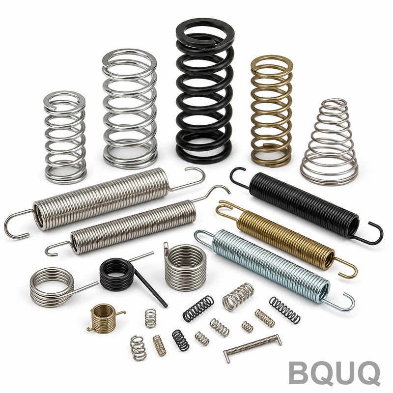
A cylindrical spring has a constant coil diameter along its entire length, producing a linear relationship between load and deflection. This means that for every additional unit of force applied, the spring compresses by the same amount, which simplifies force calculations in assembly design. Cylindrical springs are manufactured with standard coiling machines at high speeds, and typical tolerances for coil diameter are ±0.1 mm for wire diameters under 3.0 mm, with load tolerances held to ±5% of the specified value.
A conical spring, in contrast, features a coil diameter that tapers from a wide end to a narrow end. This geometry creates a progressive spring rate: as the spring compresses, the larger coils make contact with the smaller coils, effectively reducing the number of active coils and increasing stiffness. The transition from initial rate to solid height is not linear; for example, a conical spring with a 20 mm large end and 10 mm small end will show a rate increase of approximately 30% to 50% during the final third of its travel. This non-linear behavior is critical for applications requiring both a soft initial response and a firm end-of-travel stop.
How Does Solid Height Compare Between Conical and Cylindrical Springs?
Solid height is the most important dimensional difference for space-constrained designs. A cylindrical spring's solid height is calculated by multiplying the wire diameter by the total number of coils. For a spring with 8 active coils of 2.0 mm wire, the solid height is approximately 18 mm (including closed ends). A conical spring, however, nests its coils inside one another at full compression, achieving a solid height close to the wire diameter plus the thickness of one coil layer. For the same 2.0 mm wire and 8 coils, a conical spring's solid height is only about 4.0 to 5.0 mm.
This 70% reduction in solid height is the primary reason conical springs are used in automotive valve trains and mechanical seals where axial space is extremely limited. The practical trade-off is that a conical spring requires a larger radial envelope to accommodate the taper. For example, a cylindrical spring with a 25 mm diameter and 30 mm free length can achieve a solid height of 18 mm, while a conical spring with the same wire and free length might need a base diameter of 35 mm to achieve a solid height of only 5 mm. Engineers must balance axial space savings against radial space requirements.
Which Spring Design Provides a Progressive Rate and How Does It Benefit My Application?
Conical springs are the only standard spring geometry that provides a naturally progressive rate without the need for additional components like nested springs or variable-pitch winding. The progressive rate is defined by the equation: k = (G × d^4) / (8 × D^3 × N), where D changes along the coil length. As the spring compresses, the effective diameter D decreases, causing the spring constant k to increase. This results in a rate that might start at 5 N/mm and increase to 8 N/mm at 70% deflection.
This progressive behavior is highly beneficial for applications requiring a controlled transition from low to high force. For example, in a mechanical seal, a conical spring provides a low initial force for gentle contact at low pressure, then a higher force as pressure increases, preventing leakage without excessive wear. In electronics, conical springs are used in battery contacts to provide a soft insertion force and a higher retention force once the battery is fully seated. For vibration isolation, the progressive rate prevents bottoming-out under shock loads while maintaining comfort during normal operation. Cylindrical springs, with their linear rate, cannot offer this adaptive response without adding a second spring or a complex mechanical mechanism.
Why Do Conical Springs Offer Superior Resistance to Surging and Buckling?
Surging occurs when a spring's natural frequency matches the operating frequency of the machine, causing resonant vibration that leads to premature fatigue failure. The natural frequency of a cylindrical spring is constant because its mass and stiffness are distributed uniformly. For a typical valve spring with a wire diameter of 4.0 mm and 6 active coils, the natural frequency is around 450 Hz. If the engine operates at 3000 RPM (50 Hz) with a camshaft that excites the spring at 100 Hz, it is safe, but at higher speeds, surging becomes a risk.
Conical springs have a variable mass and stiffness distribution, which spreads the natural frequency over a wider range. The smaller coils at the top have a higher natural frequency, while the larger coils at the bottom have a lower one. This effectively acts as a vibration damper, with a conical spring typically showing natural frequencies 20% to 40% higher than a cylindrical spring of the same free length and wire diameter. Additionally, conical springs are inherently more resistant to buckling because the center of mass is lower and the load path is directed toward the smaller coil axis, reducing the effective slenderness ratio. For applications with operating frequencies above 300 Hz, a conical spring is the recommended choice to avoid resonance issues.
What Are the Manufacturing Cost Differences and Lead Time Implications?
Cylindrical springs are significantly cheaper to produce because they can be manufactured on high-speed automatic coiling machines at rates of 30 to 60 pieces per minute. The tooling is simple: a single mandrel and a wire guide. For a standard cylindrical compression spring of 2.0 mm wire, the unit cost is typically $0.05 to $0.15 for quantities above 10,000 pieces. Tooling cost is minimal, often under $300, and lead time for samples is 3 to 5 business days.
Conical springs require more complex coiling equipment with variable pitch control and often a CNC-controlled mandrel that changes diameter during the coiling process. Production speeds are lower, typically 10 to 20 pieces per minute, increasing unit cost by 40% to 70%. For the same 2.0 mm wire conical spring, the unit cost is $0.08 to $0.25. Tooling cost is higher, ranging from $800 to $1,500, because the mandrel must be precision-ground to the taper profile. Lead time for samples is 7 to 10 business days. If the conical spring requires grinding of both end faces to achieve a flat seat, additional labor and a secondary grinding operation are required, adding 15% to 20% to the total cost.
| Parameter | Cylindrical Spring | Conical Spring |
| Coil Diameter Tolerance | ±0.1 mm | ±0.15 mm on large end, ±0.1 mm on small end |
| Solid Height (8 coils, 2.0 mm wire) | 18.0 mm | 4.5 mm |
| Spring Rate Behavior | Linear (constant k) | Progressive (k increases 30% to 50%) |
| Natural Frequency Range | Fixed (e.g., 450 Hz) | Variable (500 to 650 Hz) |
| Unit Cost (10k+ qty, 2.0 mm wire) | $0.05 to $0.15 | $0.08 to $0.25 |
| Tooling Cost | $200 to $300 | $800 to $1,500 |
| Sample Lead Time | 3 to 5 business days | 7 to 10 business days |
| Load Tolerance | ±5% | ±7% to ±10% |
| Maximum Operating Temperature (music wire) | 120°C | 120°C |
| Maximum Operating Temperature (stainless 302) | 260°C | 260°C |
When Should I Specify a Cylindrical Spring Over a Conical Spring?
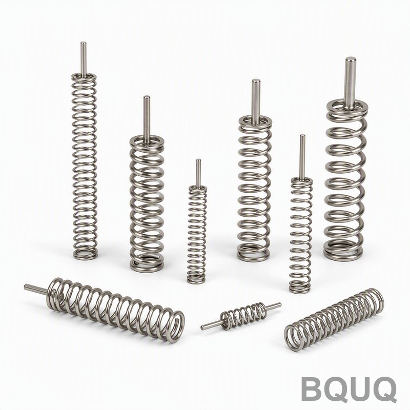
Specify a cylindrical spring when your application demands a constant, predictable force throughout the deflection range. This includes typical applications such as mechanical latches, safety valves, and simple return mechanisms where the force must remain linear. Cylindrical springs are also the correct choice when radial space is tight, as they require less radial clearance than a conical spring of equivalent free length and wire diameter. If your deflection is less than 50% of the free length and you have no space constraints on solid height, a cylindrical spring will always be more cost-effective.
Cylindrical springs should also be chosen when you require precise load tolerances of ±5% or better. The manufacturing process for conical springs introduces more variability, with load tolerances typically twice as loose as cylindrical springs due to the difficulty of holding the taper angle during coiling. For high-volume production runs above 50,000 pieces, cylindrical springs are also preferred because of their faster cycle times and lower tooling wear. If your design does not require progressive rate or minimal solid height, using a cylindrical spring will save both money and lead time.
Why Does Operating Temperature Affect the Choice Between These Spring Designs?
Temperature affects the modulus of rigidity (G) of the spring material, which directly impacts the spring rate. For both cylindrical and conical springs made from music wire (ASTM A228), the maximum continuous operating temperature is 120°C. Above this temperature, the wire loses its elastic properties and will take a permanent set. For stainless steel 302 (ASTM A313), the maximum temperature is 260°C, while chrome silicon (ASTM A401) can operate up to 230°C, and Inconel X750 up to 650°C.
The geometry of the spring, whether conical or cylindrical, does not change the material temperature limits. However, conical springs have an advantage in high-temperature applications because their progressive rate compensates for the reduction in modulus at elevated temperatures. As temperature rises, the modulus of rigidity decreases, which would soften a cylindrical spring and reduce its force. A conical spring, with its progressive rate, can be designed with a steeper taper to counteract this softening, maintaining a more stable force output across a temperature range of 20°C to 200°C. For cylindrical springs, maintaining force stability over temperature requires either a material upgrade or a redesign with additional active coils.
What Are the Key Design Calculations for a Conical Spring?
To design a conical spring, you must calculate the rate at the initial deflection and at the solid height. The initial rate (k1) is calculated using the large end diameter (D1) in the standard spring rate formula: k1 = (G × d^4) / (8 × D1^3 × N). The final rate (k2) is calculated using the small end diameter (D2): k2 = (G × d^4) / (8 × D2^3 × N). For a conical spring with D1 = 25 mm, D2 = 15 mm, d = 2.0 mm, N = 6, and G = 79.3 GPa (music wire), the initial rate is approximately 3.1 N/mm and the final rate is approximately 14.4 N/mm, a 4.6-fold difference.
The stress in a conical spring is highest at the large end coil, and the maximum shear stress is calculated using the Wahl factor: τ = K × (8 × P × D1) / (π × d^3), where K accounts for curvature and direct shear. For a load of 100 N, the stress at the large end is approximately 950 MPa, which exceeds the yield strength of music wire (around 1,400 MPa), so a safety factor of 1.5 is maintained. The solid height is calculated as the wire diameter times the total number of coils minus 0.5 for the closed ends. This calculation ensures the spring does not reach solid height before the required load is achieved, preventing coil clash and premature failure.
FAQ
Can a conical spring be used in reverse orientation in a compression application?
Yes, a conical spring can be installed with either the large end or the small end as the base, but the orientation affects the load distribution. Installing with the large end down provides better lateral stability and is the recommended orientation for most applications, while the small end down concentrates the load onto a smaller area, which can be useful for guiding but increases stress on the mating surface.
How do I measure the free length of a conical spring?
The free length of a conical spring is measured from the top of the small end coil to the bottom of the large end coil, along the central axis, with no load applied. Use a height gauge or caliper with the spring resting on a flat surface, and ensure the spring is not tilted. The free length tolerance is typically ±1.5% of the specified value or ±0.3 mm, whichever is greater.
What is the maximum compression ratio for a cylindrical spring before coil binding?
A cylindrical spring should not be compressed beyond 80% of its maximum deflection, which is the solid height minus the free length. For example, a spring with a 50 mm free length and 20 mm solid height has a maximum deflection of 30 mm, and the recommended working deflection is 24 mm or less. Exceeding this leads to coil binding and a rapid increase in stress that causes fatigue failure.
Are conical springs suitable for torsion applications?
Conical springs are generally not recommended for torsion applications because the varying coil diameter creates uneven stress distribution along the wire, leading to unpredictable torque and premature fatigue. For torsion springs, a cylindrical design with a constant diameter is the standard choice, as it provides a linear torque versus angular deflection relationship.
Which spring type has better fatigue life under cyclic loading?
A cylindrical spring has a better fatigue life under purely linear cyclic loading because the stress is distributed uniformly across all coils. A conical spring experiences higher stress concentration at the large end coil, which can reduce fatigue life by 20% to 30% if the stress is not carefully managed. For high-cycle applications exceeding 1 million cycles, cylindrical springs are preferred unless the space constraints are severe.
Can I combine a conical and cylindrical spring in one assembly?
Yes, nested spring assemblies are common in heavy-duty applications such as valve trains and suspension systems. A conical spring can be placed inside a cylindrical spring to provide a progressive overall rate while maintaining a compact axial height. Ensure that the coil directions are opposite (one left-hand, one right-hand) to prevent interlocking, and verify that the radial clearance between the springs is at least 2 mm.
How does the surface finish affect the performance of these springs?
Surface finish significantly impacts fatigue life for both spring types. Shot peening with steel shot at an intensity of 0.2 to 0.3 mm A-strength increases fatigue life by up to 30% by introducing compressive residual stress on the surface. For conical springs, shot peening is particularly important because the smaller coils have a higher surface-to-volume ratio and are more susceptible to surface cracks.
Conclusion
Selecting between a conical and cylindrical spring requires a clear evaluation of your space constraints, force requirements, and operating environment. If you need a linear force with tight tolerances and low cost, a cylindrical spring is the engineering standard. If your design demands a minimal solid height, a progressive spring rate for vibration damping, or operation in a confined axial space, a conical spring provides a unique solution that no other single spring geometry can match. At BQUQ, our engineering team has 20 years of experience in precision spring manufacturing for CNC machining and metal forming applications, and we can provide force-deflection curves and fatigue analysis for both geometries within 24 hours. For a rapid evaluation of your spring design, contact us with your working envelope, load requirements, and deflection targets to receive a quotation and design recommendation within 12 hours. Email your drawings to sc@bquq.com or message us on WhatsApp at +86 13713157787. Visit www.bquq.com to explore our manufacturing capabilities and quality certifications.


