
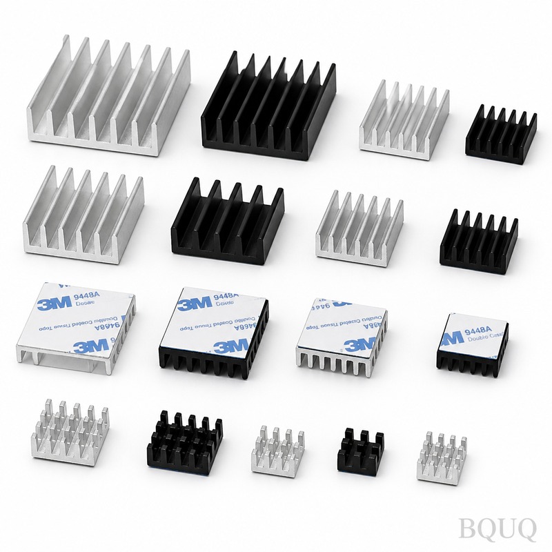
How Can Heat Sink Design Optimize Thermal Performance for Electronics?
The most effective way to optimize heat sink thermal performance is to maximize the convective surface area while minimizing the thermal resistance path from the heat source to the ambient air. This requires a precise balance of material selection, fin geometry, airflow dynamics, and mounting pressure, where a 20% increase in fin height can reduce thermal resistance by up to 15%, but only if the airflow velocity exceeds 2 m/s. For most forced-convection applications, extruded aluminum 6063-T5 heat sinks with a thermal conductivity of 200 W/mK and a base thickness of 6 mm to 10 mm provide the optimal cost-to-performance ratio, achieving case-to-ambient thermal resistances of 0.5°C/W to 5°C/W depending on size and airflow.
What Are the Primary Heat Transfer Mechanisms in Heat Sink Design?
Heat sinks dissipate thermal energy through three simultaneous mechanisms: conduction, convection, and radiation. Conduction transfers heat from the semiconductor junction through the component package, thermal interface material (TIM), and into the heat sink base, governed by Fourier's law where the thermal resistance is calculated as thickness divided by (thermal conductivity times area). Convection, typically accounting for 70% to 90% of total heat dissipation, removes heat from the fin surfaces to the surrounding air, with natural convection coefficients ranging from 5 W/m²K to 25 W/m²K and forced convection from 25 W/m²K to 250 W/m²K. Radiation contributes only 5% to 15% of total heat transfer in natural convection scenarios but becomes negligible in forced-air systems above 3 m/s airflow.
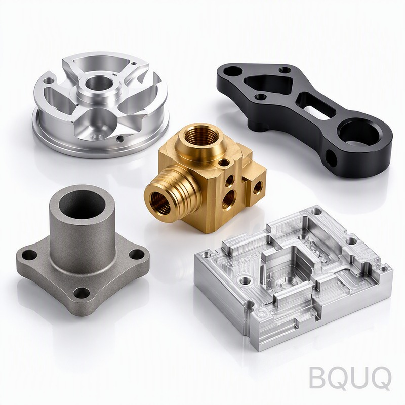
How Does Fin Geometry Affect Thermal Resistance and Pressure Drop?
Fin geometry—specifically fin height, thickness, pitch, and length—determines the surface area available for convection and the airflow resistance. For a typical extruded heat sink, increasing fin height from 20 mm to 40 mm increases surface area by 45%, but the thermal resistance decreases by only 22% because the fin efficiency drops as the temperature gradient along the fin height grows. Fin pitch (the distance between adjacent fins) should be optimized for the expected airflow: for natural convection, a pitch of 5 mm to 8 mm is ideal, while forced convection with fans above 3 m/s allows a tighter pitch of 3 mm to 5 mm. Fin thickness in extruded aluminum typically ranges from 1.2 mm to 2.0 mm, with a minimum of 1.0 mm for 6063-T5 alloy to prevent die breakage; thinner fins from skived or folded-fin processes can reach 0.2 mm to 0.5 mm but cost 30% to 50% more per unit.
Which Materials Offer the Best Thermal Conductivity for Heat Sinks?
Material selection is the primary determinant of heat sink performance, with thermal conductivity directly affecting the spreading resistance in the base and the longitudinal conduction in the fins. Copper offers a thermal conductivity of 385 W/mK, nearly double that of aluminum's 200 W/mK, and can reduce thermal resistance by 25% to 35% in the same geometry, but copper is 3.2 times denser and costs 4 to 5 times more per kilogram, making it practical only for high-power IGBT modules or laser diodes above 100 W. Aluminum alloys 6063-T5 and 6061-T6 remain the industry standard for 85% of applications due to their low cost (USD 3 to 5 per kilogram), excellent extrudability, and adequate conductivity. For high-volume applications, die-cast aluminum ADC12 (conductivity 96 W/mK) offers complex geometries but requires a 40% thicker base to compensate for the lower conductivity, while advanced materials like graphite (1000 W/mK in-plane) or vapor chambers (effective conductivity above 20000 W/mK) are reserved for compact, high-flux electronics where space is critical.
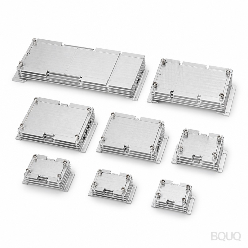
How Much Does Heat Sink Tooling Cost and What Are the Lead Times?
Tooling investment varies significantly by manufacturing process, directly impacting the total cost per unit for different production volumes. For extruded aluminum heat sinks, a standard die costs USD 800 to USD 1,500 with a lead time of 2 to 3 weeks, suitable for production runs above 500 units; custom dies with complex profiles or tight tolerances of ±0.1 mm can reach USD 3,000 to USD 5,000. Die-casting tools are substantially more expensive at USD 8,000 to USD 25,000 with 6 to 8 week lead times, justified only for volumes above 10,000 units where the per-part cost drops below USD 2.00. Bonded fin assemblies, which use epoxy or brazing to attach separate fins to a base, require no specialized tooling but carry a 20% to 30% labor premium, while CNC-machined prototypes from solid aluminum blocks cost USD 50 to USD 200 per piece with a 3 to 5 day lead time, making them ideal for design validation before committing to extrusion tooling.
What Thermal Resistance Values Can Different Heat Sink Designs Achieve?
Thermal resistance, measured in °C/W, is the definitive performance metric that engineers use to compare heat sink designs, calculated as the temperature difference between the heat sink base and ambient air divided by the power dissipated. The table below provides typical thermal resistance values for common heat sink configurations at various airflow rates, based on standard 100 mm by 100 mm base dimensions.
| Heat Sink Type | Natural Convection 0 m/s (°C/W) | Forced Air 2 m/s (°C/W) | Forced Air 4 m/s (°C/W) | Typical Cost per Unit (USD) |
| Extruded aluminum, 25 mm fin height | 2.50 | 0.80 | 0.55 | 1.80 |
| Extruded aluminum, 40 mm fin height | 1.80 | 0.55 | 0.38 | 2.60 |
| Skived copper, 20 mm fin height | 1.20 | 0.35 | 0.22 | 8.50 |
| Die-cast aluminum, 30 mm fin height | 3.20 | 1.10 | 0.75 | 1.20 |
| Folded fin aluminum, 50 mm fin height | 1.50 | 0.42 | 0.28 | 4.00 |
| Vapor chamber with aluminum fins | 0.90 | 0.25 | 0.15 | 15.00 |
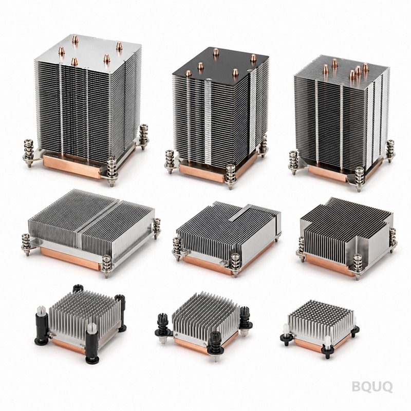
Why Does Thermal Interface Material Selection Impact Overall Performance?
The thermal interface material (TIM) between the heat source and the heat sink base is often the most overlooked source of thermal resistance, yet it can account for 30% to 50% of the total junction-to-ambient temperature rise in poorly designed systems. Phase-change materials with thermal conductivity of 3 W/mK to 8 W/mK and a bond-line thickness of 0.05 mm to 0.10 mm provide the best balance of performance and reworkability, achieving contact resistances of 0.10°C/W to 0.30°C/W for a 20 mm by 20 mm die. Thermal greases offer the lowest resistance at 0.05°C/W to 0.15°C/W but suffer from pump-out and dry-out over thermal cycling, reducing performance by up to 40% after 1000 cycles; graphite pads (conductivity 15 W/mK to 25 W/mK) are preferred for high-pressure applications above 100 psi. The mounting pressure should be maintained between 20 psi and 50 psi for optimal TIM performance, as pressures below 10 psi leave air gaps with conductivity of only 0.026 W/mK, and pressures above 80 psi risk cracking ceramic substrates.
How Should Engineers Validate Heat Sink Performance Through Testing?
Performance validation should combine computational fluid dynamics (CFD) simulation with physical testing to ensure the heat sink meets the thermal budget under real operating conditions. Using a thermal test vehicle with a resistance heater and embedded thermocouples, engineers should measure the case-to-ambient thermal resistance at three airflow points: 0 m/s (natural convection), 1 m/s, and 3 m/s (forced convection), recording steady-state temperatures after 30 minutes of soak time. CFD simulations using tools like Flotherm or Icepak can predict thermal resistance within 10% accuracy if the mesh is refined to at least 3 elements across each fin gap, but they must be calibrated with actual test data because boundary layer effects and bypass airflow around the heat sink are difficult to model precisely. Acceptance criteria should include a maximum junction temperature of 125°C for silicon devices with a 20°C safety margin, and the thermal resistance should be verified at both the rated power and at 125% of rated power to ensure derating behavior.
What Are the Most Common Heat Sink Design Mistakes to Avoid?
The most frequent design errors include undersizing the base thickness, which causes excessive spreading resistance when the heat source is smaller than the heat sink base; a base thickness below 5 mm for a 50 mm by 50 mm heat source can increase total thermal resistance by 30%. Another critical error is orienting fins parallel to the natural airflow direction in passive systems, which reduces convection by 40% compared to vertical fin orientation, and placing the heat sink too close to enclosure walls, where a clearance of less than 10 mm creates a thermal blockage that raises ambient temperature around the fins by 15°C. Engineers also frequently specify excessive fin density for natural convection applications, where a pitch below 4 mm prevents the buoyancy-driven airflow from penetrating the fin array, effectively creating a solid block of aluminum with no convective benefit.
FAQ
What Is the Maximum Heat Dissipation Capacity of an Aluminum Heat Sink?
A standard extruded aluminum heat sink with a 100 mm by 100 mm base and 40 mm fin height can dissipate 50 W to 80 W in natural convection and 150 W to 250 W with forced airflow of 3 m/s, maintaining a 40°C to 60°C temperature rise above ambient. For higher dissipation, copper heat sinks or heat pipe-assisted designs are required, which can handle 300 W to 500 W in the same footprint.
How Do I Calculate the Required Heat Sink Thermal Resistance?
Divide the allowable temperature rise (junction temperature minus maximum ambient temperature) by the power dissipation, then subtract the junction-to-case resistance and the TIM resistance. For example, a 100 W device with a 125°C junction limit and 50°C ambient must have a total resistance of 0.75°C/W; after subtracting 0.15°C/W for the package and 0.10°C/W for the TIM, the heat sink must provide 0.50°C/W or less.
When Should I Use a Heat Pipe Instead of a Solid Heat Sink?
Use a heat pipe when the heat source is located in a confined space far from the available cooling surface, requiring heat to be transported over distances greater than 50 mm. Heat pipes have effective thermal conductivities above 5000 W/mK and can transfer 50 W to 200 W per pipe with a temperature drop of less than 5°C, making them ideal for laptop CPUs, LED streetlights, and telecommunication base stations.
Can I Use Anodized Aluminum for Better Heat Dissipation?
Anodizing increases the surface emissivity from 0.05 for bare aluminum to 0.80 for black anodized surfaces, improving radiation heat transfer by up to 15% in natural convection applications. However, the anodic coating adds only 0.02°C/W thermal resistance and provides negligible benefit in forced-air systems where convection dominates.
How Does Altitude Affect Heat Sink Performance?
At altitudes above 3000 meters, air density decreases by 30%, which reduces convective heat transfer coefficients proportionally, requiring a heat sink with 30% lower thermal resistance to maintain the same junction temperature. For aerospace or high-altitude applications, engineers should increase fin surface area by 25% to 40% or specify a higher airflow fan to compensate for the reduced air density.
At BQUQ, we have manufactured precision heat sinks for over 20 years, combining CNC machining, metal stamping, and extrusion processes to deliver thermal solutions with tolerances as tight as ±0.05 mm. Our engineering team provides free thermal simulation and design optimization with every quotation, ensuring your heat sink meets the thermal budget at the lowest possible cost. Submit your drawings or power dissipation requirements today for a 12-hour quotation; contact us at sc@bquq.com or WhatsApp +86 13713157787, or visit www.bquq.com for our full manufacturing capabilities.


