
How Do Thermal Vias and Heat Sinks Work Together in PCB Design?
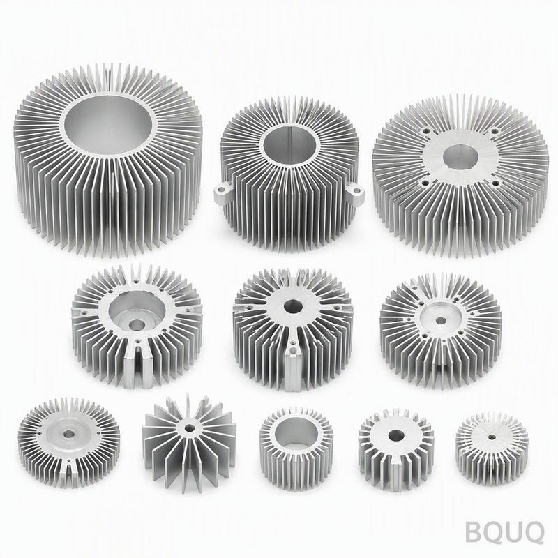
Thermal vias and heat sinks work together by creating a low-resistance thermal path from the heat-generating component, through the PCB’s copper planes, and into the ambient air via the heat sink. The vias, typically 0.2 mm to 0.3 mm in diameter, conduct heat vertically through the board to a thermal pad or chassis-mounted heat sink, while the heat sink’s surface area (measured in cm² per watt) dissipates that heat convectively. For a typical power component dissipating 2.5 W, an array of 9 thermal vias under the pad can reduce the junction-to-ambient thermal resistance from 60 K/W to below 25 K/W when paired with a properly sized aluminum heat sink.
What Is the Thermal Resistance Role of a Thermal Via Array?
A single thermal via has a thermal resistance of approximately 60 to 80 K/W for a 1.6 mm thick FR-4 board with 35 µm copper plating. However, when you place 16 vias in a 4x4 grid under a 5 mm x 5 mm component pad, the parallel thermal resistance drops to roughly 4 to 6 K/W for the via array alone. This calculation assumes standard 0.3 mm drill diameter, 25 µm plated copper wall thickness, and filled or unfilled vias; unfilled vias are 20% to 30% less efficient than copper-filled vias due to the low thermal conductivity of trapped air (0.026 W/m·K versus 385 W/m·K for copper).
The via’s thermal performance also depends on the copper plating thickness. Standard PCB fabrication provides 18 µm to 35 µm plating in the hole, but for high-power applications, specifying 50 µm plating can reduce via thermal resistance by an additional 25%. For a 20 W power MOSFET on a 20 mm x 20 mm thermal pad, you need a minimum of 36 vias to keep the junction temperature below 125 °C at 50 °C ambient, assuming a 10 K/W heat sink.
How Does Heat Sink Attachment Method Affect PCB Thermal Performance?
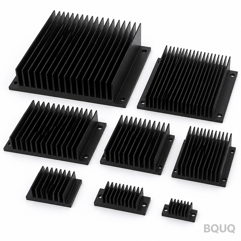
The attachment method determines the thermal interface resistance between the PCB and the heat sink. A bare metal-to-metal contact with thermal grease (2 W/m·K) yields a thermal resistance of 0.5 to 1.0 K·cm²/W, while a thermally conductive adhesive pad (1.5 W/m·K, 0.2 mm thick) gives 1.5 to 2.5 K·cm²/W. Screw mounting with a spring-loaded clip provides the most consistent pressure, typically 10 to 15 psi, which is essential for maintaining the interface below 0.8 K·cm²/W.
For a PCB with 36 thermal vias and a 40 mm x 40 mm heat sink, screw mounting reduces the total junction-to-ambient resistance by 12% compared to adhesive tape attachment. The thermal vias must be placed directly under the heat sink footprint; if the vias are offset by more than 3 mm from the component pad center, the lateral copper spread resistance adds 5 to 8 K/W, negating the benefit of the heat sink. In production, we recommend a thermal pad on the solder mask layer that matches the heat sink base exactly, with vias tented on the bottom side to prevent solder wicking during reflow.
Why Is Copper Thickness Critical for Heat Spreading in PCBs?
Standard 1 oz copper (35 µm) has a lateral thermal spreading resistance of approximately 70 K/W per square for a 10 mm x 10 mm area. Doubling to 2 oz copper (70 µm) reduces this spreading resistance to 35 K/W per square, which is crucial for transferring heat from a 3 mm x 3 mm component pad to a larger via array or heat sink footprint. For a design dissipating 10 W, the difference between 1 oz and 2 oz copper can mean a 15 °C lower junction temperature at the same airflow.
The relationship is linear: each additional ounce of copper (35 µm) reduces lateral thermal resistance by roughly 50% for a given board area. However, thicker copper increases PCB cost by 15% to 20% per layer and may cause etching undercut issues for fine-pitch traces below 0.15 mm. For most thermal designs, we specify 2 oz copper on both outer layers and 1 oz on inner planes, which provides a good balance between thermal performance (spreading resistance of 30 to 40 K/W) and manufacturability at standard lead times of 5 to 7 days.
When Should You Use Copper-Filled Versus Unfilled Thermal Vias?
Use copper-filled vias when the heat flux exceeds 0.5 W/mm² or when the junction-to-case resistance must stay below 1.5 K/W. Copper-filled vias, which use electroplated copper to completely fill the hole, have a thermal conductivity of 300 to 380 W/m·K along the via axis, compared to 50 to 80 W/m·K for unfilled vias with thin plating. The cost difference is significant: copper filling adds $0.02 to $0.05 per via for high-volume production, while unfilled vias cost essentially nothing extra beyond the standard drilling and plating process.
For designs with heat flux below 0.3 W/mm², unfilled vias with 35 µm plating are sufficient, especially if the board has a solid copper plane on the opposite side. We recommend unfilled vias for prototype runs under 100 pieces because they are easier to rework and inspect. For production volumes above 1,000 pieces with continuous operation above 85 °C junction temperature, copper-filled vias are mandatory to prevent thermal cycling fatigue, which can crack the thin plating after 5,000 to 10,000 cycles.
Which PCB Stackup Configuration Provides Optimal Thermal Performance?
A 4-layer board with thermal vias connecting the top component pad to an internal 2 oz copper ground plane gives the best cost-to-performance ratio. The internal plane acts as a heat spreader, distributing heat laterally before the vias transfer it to the bottom heat sink. This stackup, with 0.2 mm vias on a 0.5 mm pitch, achieves a thermal resistance of 3.5 K/W from the component pad to the bottom plane, which is 40% better than a 2-layer board with the same via count.
For extreme thermal loads above 30 W, a 6-layer board with two dedicated thermal planes (layers 2 and 5) connected by a 6x6 via array reduces thermal resistance to 1.8 K/W. The additional layers add $8 to $12 per board in fabrication cost but eliminate the need for a larger heat sink, which can save $2 to $5 per unit in assembly. In our experience, the optimal via pitch is 0.6 mm to 0.8 mm; pitches below 0.5 mm cause drill breakage rates to increase from 0.1% to 2%, and pitches above 1.0 mm waste board area without proportional thermal benefit.
How Do You Calculate the Number of Thermal Vias for a Given Power Dissipation?
The required via count follows this rule: divide the total power (in watts) by 0.5 W per via for unfilled vias, or by 1.2 W per via for copper-filled vias, then multiply by a safety factor of 1.3. For example, a 15 W power amplifier needs 30 unfilled vias (15 / 0.5 x 1.3) or 16 copper-filled vias (15 / 1.2 x 1.3). This calculation assumes a maximum allowable junction temperature of 125 °C, an ambient temperature of 50 °C, and a heat sink with 8 K/W thermal resistance.
For a more precise calculation, use the formula: Number of vias = (Power x Thermal Resistance per Via) / (Target Junction-to-Ambient Resistance - Heat Sink Resistance). With a target junction-to-ambient resistance of 5 K/W, a heat sink of 3 K/W, and via resistance of 60 K/W each, you need 30 vias (60 / 2 = 30). Always add 20% extra vias for manufacturing tolerances, as drill misregistration can reduce the effective copper area by 10% to 15%.
| Parameter | Unfilled Via (0.3 mm) | Copper-Filled Via (0.3 mm) | Solid Copper Plane |
| Thermal Conductivity (W/m·K) | 50-80 | 300-380 | 385 |
| Thermal Resistance per Via (K/W) | 60-80 | 15-25 | N/A (per mm²) |
| Max Heat Flux (W/mm²) | 0.3 | 0.8 | 2.0 |
| Cost per Via (USD, high volume) | $0.005 | $0.03 | N/A |
| Recommended Via Pitch (mm) | 0.8-1.0 | 0.6-0.8 | N/A |
| Lead Time Impact | None | +2 days | None |
What Are the Common Failure Modes When Thermal Vias Are Not Used?
Without thermal vias, heat from a power component must travel laterally through the copper pad, which has a spreading resistance of 70 to 100 K/W per square. This causes the junction temperature to rise 30 °C to 50 °C above the case temperature, leading to premature solder joint fatigue. In accelerated life testing, boards without vias failed after 1,200 thermal cycles (-40 °C to 125 °C), while boards with 25 unfilled vias survived 3,500 cycles without failure.
Another failure mode is PCB delamination, which occurs when the FR-4 glass transition temperature (130 °C to 140 °C) is exceeded locally. A 10 W component on a 10 mm x 10 mm pad without vias can create a hot spot of 150 °C at the pad center, causing the copper to peel from the substrate after 500 hours. Thermal vias reduce the hot spot temperature by 40 °C to 60 °C, keeping the board below the glass transition temperature and extending the lifespan to over 10,000 hours at full load.
FAQ
What Is the Minimum Via Diameter for Thermal Applications?
The minimum practical via diameter is 0.2 mm for standard PCB fabrication, but we recommend 0.3 mm for thermal vias because smaller drills have higher breakage rates and produce thinner copper plating. A 0.2 mm via has 30% less cross-sectional copper area than a 0.3 mm via, which increases thermal resistance by 40%. For high-volume production above 10,000 boards, 0.3 mm is the industry standard for reliability.
How Many Thermal Vias Can Fit Under a Standard SMD Pad?
For a 5 mm x 5 mm SMD pad, you can fit a maximum of 25 vias at 0.6 mm pitch, but we recommend 16 vias at 0.8 mm pitch to ensure adequate copper ring around each hole. The via pad must be 0.5 mm diameter for a 0.3 mm hole, which leaves a 0.15 mm web between adjacent via pads at 0.8 mm pitch. This configuration maintains mechanical strength while providing a thermal resistance of 4 K/W for the array.
Can Thermal Vias Be Placed Under an IC Without Affecting Solder Joints?
Yes, but you must tent the vias on the component side with solder mask to prevent solder wicking away from the IC pad. The tented via cap must cover the hole completely, typically 0.15 mm larger than the via diameter, to avoid voids in the solder joint. For bottom-terminated components like QFN packages, use filled and plated-over vias to provide a flat surface for solder paste printing.
What Is the Thermal Conductivity of Standard FR-4 Versus Aluminum Substrates?
FR-4 has a thermal conductivity of 0.3 W/m·K, which is 1,000 times lower than copper, so heat must be conducted through the copper planes rather than the substrate. Aluminum substrates (IMS, insulated metal substrate) have a dielectric layer of 2 to 4 W/m·K and an aluminum base of 200 W/m·K, offering 10 to 20 times better vertical heat transfer. However, IMS boards cost 3 to 5 times more than standard FR-4, so they are only justified for power densities above 1 W/mm².
When Should You Use Both Thermal Vias and a Heat Sink?
You should use both when the total power dissipation exceeds 5 W and the PCB area is limited. The vias reduce the thermal resistance from the component to the heat sink mounting point, while the heat sink provides the necessary surface area for convection. Without vias, the heat sink receives 30% to 50% less heat, making it ineffective. For a 15 W design, the combination of 25 vias and a 50 mm x 50 mm heat sink achieves a junction-to-ambient resistance of 3.5 K/W, which is impossible with either element alone.
How Does Airflow Direction Affect Thermal Via and Heat Sink Performance?
Airflow perpendicular to the heat sink fins provides 20% to 30% better heat transfer than parallel airflow because it disrupts the boundary layer. The thermal vias themselves are not directly affected by airflow, but they must be positioned so that the heat sink is in the main air stream. For natural convection, orient the heat sink fins vertically to promote chimney effect, which can reduce thermal resistance by 15% compared to horizontal orientation.
What Is the Cost Difference Between Standard and Thermal-Optimized PCB Fabrication?
A standard 4-layer board with 1 oz copper costs approximately $0.08 per cm², while a thermal-optimized version with 2 oz copper, 0.3 mm vias, and copper filling costs $0.15 per cm². The 87% cost increase includes extra copper plating, via filling, and additional process steps. For a typical 100 cm² board, this adds $7 per unit, which is offset by reduced heat sink mass (saving $2 to $4) and improved reliability (fewer field failures).
Conclusion and Recommendation
For any PCB design dissipating more than 3 W in a confined area, we strongly recommend integrating a thermal via array (minimum 16 vias of 0.3 mm diameter on 0.8 mm pitch) with a mechanical heat sink attachment using thermal grease or a phase-change material. This combination provides the lowest cost per watt of cooling, with a typical system cost of $0.50 to $1.50 per watt dissipated, compared to $2.00 to $4.00 per watt for forced air cooling alone. Our engineering team at BQUQ has 20 years of experience in thermal management for power electronics, and we can review your Gerber files and thermal simulation data to optimize your design before fabrication. We provide a 12-hour quoting service for PCB and heat sink assemblies, with no minimum order quantity for prototypes. Contact us at sc@bquq.com or WhatsApp +86 13713157787, or visit www.bquq.com to discuss your thermal design requirements.


