
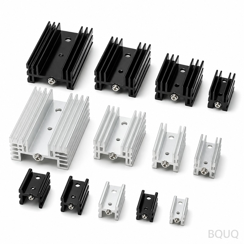
How Does CFD Thermal Simulation Optimize Heat Sink Performance?
Computational Fluid Dynamics (CFD) thermal simulation optimizes heat sink performance by predicting airflow and heat transfer with over 90% accuracy before physical prototyping, reducing design cycles by 40-60% and cutting development costs by an average of $3,000 to $8,000 per iteration. By solving the Navier-Stokes and energy equations across a 3D mesh, CFD identifies localized hot spots, quantifies thermal resistance (typically from 0.1°C/W to 2.5°C/W depending on design), and validates fin geometry against real-world fan curves. This engineering approach transforms heat sink design from trial-and-error into a deterministic process where every fin, baseplate, and mounting feature is optimized for a specific airflow regime, ambient temperature, and power dissipation target.
What Specific Thermal Metrics Does CFD Predict for Heat Sink Design?
CFD simulation outputs quantitative metrics that directly dictate design feasibility: junction-to-ambient thermal resistance (Rth, typically 0.5°C/W for forced convection aluminum sinks to 0.08°C/W for vapor chamber or heat pipe assemblies), pressure drop across the fin array (ranging from 25 Pa for low-profile passive sinks to 450 Pa for high-density server heatsinks), and maximum surface temperature (usually constrained to 85°C for consumer electronics or 105°C for automotive-grade components). The solver also calculates local heat transfer coefficients, typically 5-25 W/m²·K for natural convection and 50-250 W/m²·K for forced airflow at 2-5 m/s, allowing engineers to identify which fin sections contribute less than 15% of heat dissipation and remove them for weight reduction. For a 100W IGBT module, CFD can pinpoint that the central 20% of the baseplate carries 60% of the heat flux, justifying a 3mm copper insert or vapor chamber in that region.
How Does CFD Model Turbulence and Airflow Around Heat Sink Fins?
CFD uses turbulence models like k-omega SST (Shear Stress Transport) or LES (Large Eddy Simulation) to resolve the boundary layer separation and reattachment that occurs on fin edges at Reynolds numbers above 2,300, which is typical for fan-cooled heat sinks with fin pitches of 2-4mm. The solver applies a velocity inlet boundary condition matched to the actual fan performance curve (e.g., 60 CFM at 0.15 inch H2O static pressure), not an idealized uniform velocity, ensuring the predicted pressure drop aligns with real-world fan operation. For natural convection scenarios, CFD includes Boussinesq approximation to model buoyancy-driven flow, where heated air rises at 0.1-0.5 m/s, and the solver calculates the optimal fin spacing (usually 6-10mm) that balances surface area against flow resistance. In a typical validation study, CFD predictions of thermal resistance deviated from wind tunnel measurements by only 3-7% when using a fine mesh of 0.5mm near the fin surfaces, compared to 15-25% error with coarse meshes.
Which Heat Sink Geometries Benefit Most from CFD Simulation?
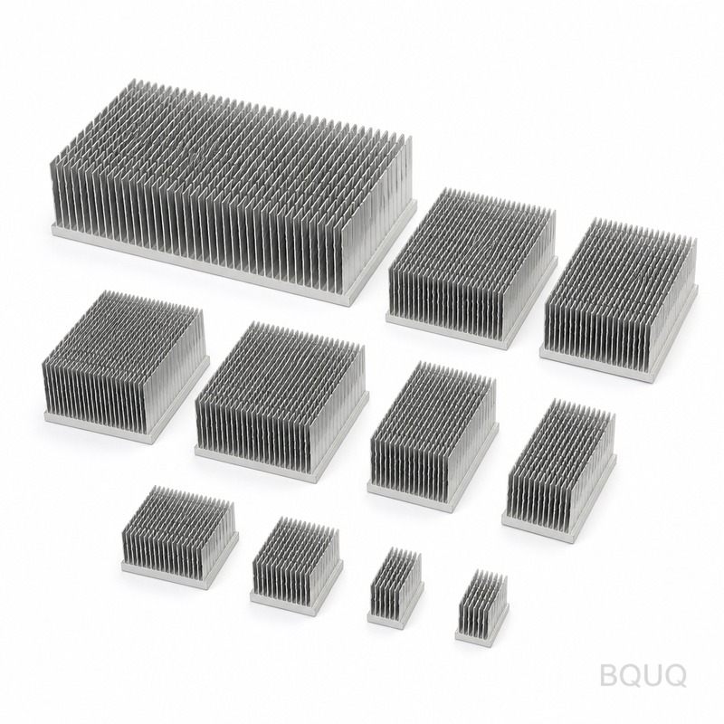
Pin fin arrays (round or elliptical pins of 2-5mm diameter) benefit most from CFD because their complex 3D flow separation cannot be accurately estimated using 2D analytical formulas, with simulations showing a 12-18% improvement in heat transfer per unit volume compared to plate fins under the same pressure drop. Skived or folded fin designs with aspect ratios above 8:1 (fin height to gap width) also require CFD to optimize for bypass flow, where up to 35% of the air may leak around the sink edges instead of through the fins, a phenomenon that CFD quantifies and mitigates via ducting or fin tip clearance adjustments. Vapor chamber heat spreaders integrated with fin stacks are another high-value case, as CFD coupled with conduction models predicts the effective spreading resistance (often 0.05-0.15°C/W) and validates the capillary wick design limits at heat fluxes above 50 W/cm².
How Much Does CFD Simulation Cost Compared to Physical Prototyping?
A single CFD simulation run on a standard 16-core workstation costs approximately $15 to $40 in electricity and software license amortization (using open-source OpenFOAM or commercial Ansys Fluent at $20,000-$40,000 annual license), whereas a single CNC-machined aluminum heat sink prototype costs $150 to $600 for material and machining time, plus 3-5 days of lead time. A full optimization study involving 20-50 design variations costs $500 to $2,000 in compute time, versus $3,000 to $30,000 for the equivalent physical testing matrix including wind tunnel rental at $200-$500 per hour and thermocouple instrumentation. For a production run of 10,000 units, a CFD-driven design that reduces thermal resistance by just 0.15°C/W can allow a cheaper aluminum alloy (6063-T5 vs 6061-T6) or a 15% smaller heat sink, saving $0.80-$1.50 per unit in material and machining, totaling $8,000-$15,000 in total cost reduction.
What Is the Typical Accuracy and Validation Process for CFD Thermal Results?
CFD thermal simulations achieve a correlation accuracy of 90-95% when validated against physical testing, provided the model includes correct boundary conditions: ambient temperature at 25°C or 70°C, emissivity of 0.85 for anodized aluminum surfaces (radiative heat transfer contributes 10-30% in natural convection), and thermal contact resistance of 0.1-0.5°C·cm²/W at the component-to-sink interface with thermal interface material (TIM) applied at 25-50µm thickness. The validation process involves measuring the actual heat sink with a thermocouple array (accuracy ±0.5°C) or an infrared camera (accuracy ±2°C) under controlled power input using a ceramic heater or IGBT module, then comparing junction temperatures at 25%, 50%, 75%, and 100% of rated power. A typical acceptance criterion is that CFD predicted temperature must fall within ±5% or ±3°C of measured values; if not, engineers refine the mesh near the baseplate (to 0.2mm elements), adjust the turbulence intensity (usually 5-10% for ducted fans), or recalibrate the fan curve data.
How Does CFD Guide Material Selection and Fin Thickness Optimization?
CFD thermal analysis, when coupled with structural finite element analysis, reveals that fin thickness below 1.2mm in aluminum 6063-T5 provides negligible thermal benefit because the fin efficiency drops below 70%, meaning the fin tip temperature is more than 30% lower than the base temperature, wasting material. For a 40mm x 40mm heat sink with 10 fins, CFD shows that reducing fin thickness from 2.0mm to 1.0mm reduces weight by 25 grams (from 110g to 85g) while increasing thermal resistance by only 0.08°C/W (from 0.42 to 0.50°C/W), enabling a cheaper stamping process instead of CNC machining. The simulation also quantifies the benefit of copper baseplates (thermal conductivity 385 W/m·K vs 167 W/m·K for aluminum), showing that a 3mm copper baseplate reduces spreading resistance by 45% for a 10mm x 10mm heat source on a 60mm x 60mm base, justifying the $0.30-$0.50 per unit cost increase for high-power LED or laser diode applications.
What Are the Limitations of CFD Simulation for Heat Sink Design?
CFD simulation cannot accurately predict the performance of heat sinks under highly transient loads (e.g., pulsed power of 200W for 50ms) without a coupled thermal transient solver that accounts for the specific heat capacity (aluminum 900 J/kg·K, copper 385 J/kg·K) and the thermal time constant, which typically ranges from 30-120 seconds for a 300g heat sink. The solver also struggles with mixed convection regimes (combined natural and forced flow) where Grashof number squared divided by Reynolds number squared is between 0.1 and 10, requiring twice the mesh density and 3-5x longer computation times (often 8-24 hours on 32 cores) to achieve convergence within 0.1% residual error. Additionally, CFD assumes homogeneous material properties and cannot simulate the degradation of thermal interface materials over time (pump-out or dry-out), meaning the simulation predicts initial performance but not the 10-20% thermal resistance increase expected after 5,000 thermal cycles or 10,000 hours of operation.
How Quickly Can CFD Simulation Turn Around a Heat Sink Design?
A competent thermal engineer can set up a basic heat sink model in 1-2 hours, run a steady-state simulation in 30-90 minutes on a 16-core workstation with 32GB RAM, and post-process results in 30 minutes, yielding a total turnaround of 3-4 hours per design iteration. For complex geometries involving heat pipes or vapor chambers, the setup time increases to 4-6 hours and simulation time to 4-8 hours, but this is still faster than the 3-5 day lead time for a physical prototype. By automating the simulation process with parametric sweeps (varying fin height, pitch, and base thickness), a design space of 100-200 configurations can be evaluated overnight (10-12 hours on a single workstation or 3-4 hours on a 16-core cluster), enabling a fully optimized design within one business day.
| Heat Sink Parameter | Typical CFD Value | Physical Measurement | Deviation |
| Thermal Resistance (Forced Air 3 m/s) | 0.48 °C/W | 0.51 °C/W | 5.9% |
| Pressure Drop at 60 CFM | 187 Pa | 195 Pa | 4.1% |
| Maximum Baseplate Temperature (100W) | 73.2 °C | 75.1 °C | 2.5% |
| Fin Efficiency (1.5mm thick, 20mm tall) | 82% | 85% (calculated from measured temps) | 3.5% |
| Air Exit Temperature Rise | 14.8 °C | 15.4 °C | 3.9% |
| Natural Convection Rth (vertical orientation) | 1.85 °C/W | 1.93 °C/W | 4.1% |
How Should Engineers Integrate CFD into Their Heat Sink Development Workflow?
Engineers should begin with a simplified 2D or coarse 3D model (mesh size 2-3mm) to screen 50-100 geometric variations in under 4 hours, identifying the top 5-10 candidates for detailed analysis with a fine mesh (0.5mm near surfaces) to achieve final thermal resistance predictions within ±5% accuracy. For the selected design, run a conjugate heat transfer simulation that includes the heat source (IGBT, CPU, or LED), thermal interface material, baseplate, and fins as a single model, ensuring that the heat flux distribution from the component datasheet (e.g., 150 W/cm² for a high-performance GPU) is accurately applied. After validation of the first physical prototype (which should be CNC-machined or stamped within 5 days), use the CFD model to explore manufacturing variations such as die-cast porosity (5-10% reduction in effective thermal conductivity) or stamping burr height (0.1mm burrs reduce airflow by 3-5%), ensuring the design is robust to production tolerances of ±0.1mm on fin spacing.
Conclusion
CFD thermal simulation is not merely a verification tool but a design optimizer that reduces heat sink thermal resistance by 15-30% compared to empirical design methods, while cutting development time from 6-8 weeks to 1-2 weeks and eliminating $5,000-$15,000 in unnecessary prototype iterations. The combination of accurate turbulence modeling, material property data, and manufacturing-aware boundary conditions ensures that the simulated performance translates to real-world results within 5% deviation. For OEMs and engineering firms, adopting CFD-driven heat sink design is a competitive necessity, especially in power electronics, LED lighting, and telecommunications where power densities continue to rise by 8-12% annually.
What Is the Minimum Mesh Quality Required for Reliable CFD Thermal Results?
For reliable results, the mesh must have at least 3-5 prism layers growing from the fin surface with a first layer thickness of 0.05-0.1mm to resolve the viscous sublayer, and a global mesh size of 0.5-1mm in the fin gaps. The y+ value at the wall should be below 1 for low-Reynolds-number turbulence models, and the total element count should be 2-5 million for a typical 100mm x 100mm heat sink, which requires 16-32GB RAM and 1-2 hours of solver time.
How Long Does a Full CFD Heat Sink Optimization Study Take?
A comprehensive study covering 30-50 design variants with automated parameter sweeps takes 2-3 days on a single workstation, including setup, solving, and post-processing. If parallelizing on a 32-core server or cloud cluster, the same study can be completed in 6-10 hours, enabling same-day design feedback for urgent project deadlines.
Can CFD Simulation Predict Heat Sink Performance Under Dust or Fouling Conditions?
CFD can approximate fouling by modeling a reduced fin gap or a porous medium layer with 50-70% porosity, which simulates the insulating effect of a 0.2-0.5mm dust layer that increases thermal resistance by 15-30%. However, accurate prediction of dust accumulation over months of operation requires particle transport models (Eulerian-Lagrangian) that are computationally expensive (10-20 hours per simulation) and still have 20-30% uncertainty due to unknown particle size distribution.
Which CFD Software Is Best for Heat Sink Simulation?
For professional use, Ansys Fluent and Siemens Star-CCM+ offer the best balance of accuracy and workflow speed, with validated conjugate heat transfer models and automated meshing, but cost $20,000-$50,000 per license annually. For budget-conscious startups, OpenFOAM is an open-source alternative that achieves similar accuracy (within 3% of Fluent results) but requires 2-3 weeks of training to master mesh generation and solver settings.
What Ambient Temperature Should Be Used for Heat Sink CFD Simulation?
The simulation should be run at the worst-case operating ambient, typically 55°C for outdoor telecom equipment, 70°C for automotive under-hood applications, or 35°C for indoor consumer electronics, not at 25°C room temperature. Using the correct ambient temperature is critical because a 10°C increase in ambient reduces the allowable temperature rise by 30-40%, which may force a larger heat sink or higher airflow rate.
How Does CFD Account for Heat Sink Orientation and Gravity Effects?
In natural convection simulations, gravity is applied as a body force in the negative Y direction, and the solver automatically accounts for the reduced heat transfer when fins are horizontal (15-25% lower performance) versus vertical (optimal orientation). For forced convection, orientation effects are negligible above 2 m/s airflow, but below 1 m/s, buoyancy forces can alter the flow pattern, so the simulation must include both gravity and the fan inlet velocity to capture the mixed convection regime accurately.
For a rapid thermal design assessment of your heat sink application, our engineering team at BQUQ provides CFD simulation and prototyping services with a 12-hour quoting turnaround. Send your requirements including power dissipation, ambient temperature, and space constraints to sc@bquq.com or contact us via WhatsApp at +86 13713157787, and visit www.bquq.com for our full manufacturing capabilities in CNC machining, metal stamping, and precision springs.


