
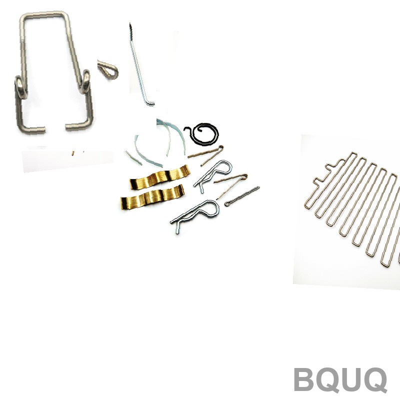
How to Design a Compression Spring: Step-by-Step Guide for CNC and Stamping Engineers
Designing a compression spring for precision manufacturing requires a calculated balance of material properties, geometric constraints, and load requirements. This guide provides a direct engineering methodology: first define the force-deflection curve, then select the wire diameter and mean coil diameter, calculate the spring rate, verify stress and buckling, and finalize with tolerance specifications. For a standard steel compression spring in a 20 mm bore, expect a lead time of 3 to 5 days for CNC coiling and 7 to 10 days for fully ground, stress-relieved springs.
Step 1: Define Operating Parameters and Load Requirements
Before any calculation, establish the three critical operating points: the free length (L0), the load at a preload height (L1), and the load at the maximum compressed height (L2). The difference between these loads divided by the deflection gives the spring rate (k). For example, if you need 50 N at a height of 40 mm and 100 N at a height of 30 mm, the spring rate is (100-50) N / (40-30) mm = 5 N/mm. This rate is the foundation of the entire design.
For dynamic applications, define the operating frequency. A compression spring must operate below 80% of its natural frequency to avoid surging. The natural frequency (f) in Hz is approximately f = 356,000 * d / (D^2 * N_a), where d is wire diameter in mm, D is mean coil diameter in mm, and N_a is the number of active coils. For a wire of 2 mm, mean diameter of 12 mm, and 8 active coils, the frequency is approximately 356,000 * 2 / (144 * 8) = 618 Hz.
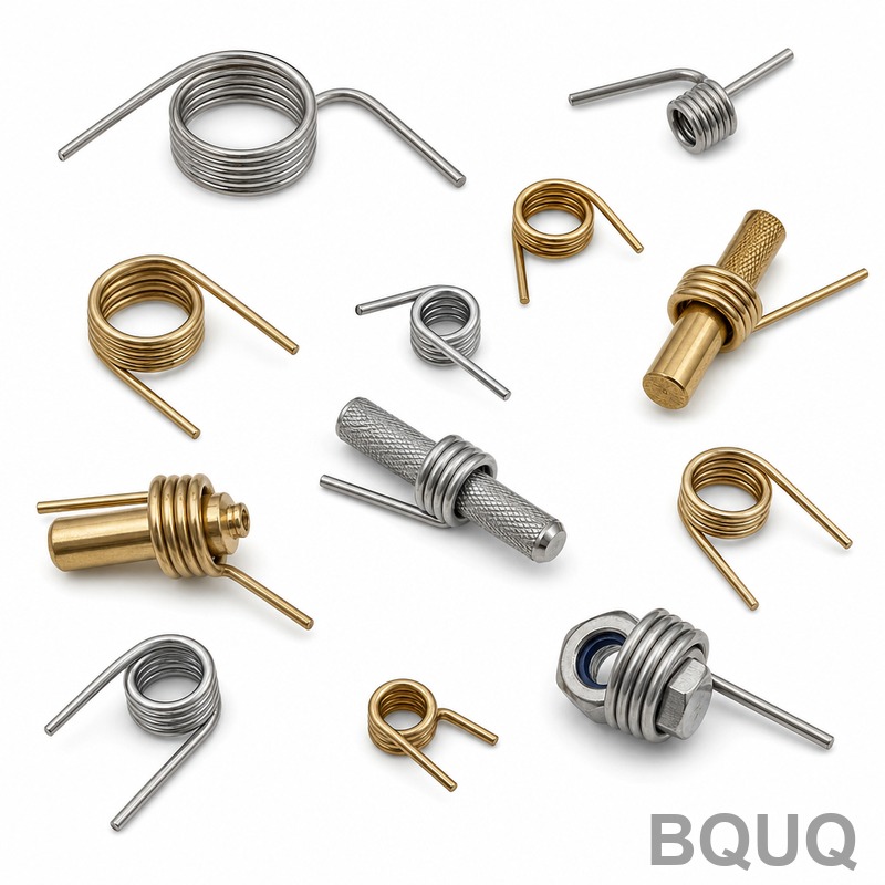
Material Selection: Wire Grade and Temperature Limits
Material choice dictates maximum stress, temperature range, and cost. For general industrial use, oil-tempered chrome-silicon steel (ASTM A401) offers a tensile strength of 1,800 to 2,000 MPa and operates up to 200°C. Stainless steel 302 (AISI 302) provides corrosion resistance but lower strength (1,200 to 1,500 MPa) and a temperature limit of 150°C. For high-temperature environments above 250°C, use Inconel X-750, which retains 70% of its room-temperature strength at 540°C.
The maximum allowable shear stress should be 45% of the ultimate tensile strength for static service and 30% for dynamic service. For a music wire (ASTM A228) with 2,200 MPa tensile strength, the static allowable stress is 990 MPa, but the dynamic allowable stress drops to 660 MPa. Our factory recommends chrome-silicon for automotive valve springs and 302 stainless for medical or food-contact parts.
| Material Grade | Tensile Strength (MPa) | Max Temp (°C) | Max Shear Stress Static (MPa) | Relative Cost Index |
| Wire diameter 2.0 mm | 2,200 (Music Wire) | 120 | 990 | 1.0 |
| Chrome-silicon ASTM A401 | 1,900 | 200 | 855 | 1.4 |
| Stainless 302 | 1,350 | 150 | 607 | 1.8 |
| Inconel X-750 | 1,000 | 540 | 450 | 5.5 |
Step 2: Calculate Spring Geometry and Spring Rate
Using the chosen wire diameter (d) and mean coil diameter (D), calculate the spring index (C = D/d), which should be between 4 and 12 for manufacturability. A spring index below 4 causes high stress concentration and tool wear; above 12 makes the spring unstable and prone to buckling. For a wire of 2 mm and mean diameter of 12 mm, C = 6, which is optimal.
The spring rate (k) is calculated using the formula k = (G * d^4) / (8 * D^3 * N_a), where G is the shear modulus (79,300 MPa for steel). To achieve 5 N/mm with d = 2 mm and D = 12 mm, solve for N_a: N_a = (79,300 * 16) / (8 * 1,728 * 5) = 18.4 active coils. Add 2 inactive coils for closed and ground ends, giving a total of 20.4 coils.
The solid height (Ls) is the product of total coils and wire diameter: 20.4 * 2 = 40.8 mm. Ensure the maximum compressed height (L2) is at least 15% greater than Ls to prevent coil binding. If L2 = 30 mm, this design is invalid because 30 mm is less than 40.8 mm. You must reduce N_a or increase the wire diameter. Redesign with d = 2.5 mm and D = 15 mm: N_a = (79,300 * 39.06) / (8 * 3,375 * 5) = 22.9 coils, solid height = 24.9 * 2.5 = 62.3 mm, which still exceeds 30 mm. The proper solution is to use a larger mean diameter or accept a lower spring rate.
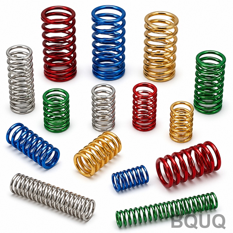
Step 3: Stress Verification and Buckling Check
Calculate the Wahl factor (Kw) to account for curvature stress: Kw = (4C - 1) / (4C - 4) + 0.615 / C. For C = 6, Kw = (24-1)/(24-4) + 0.615/6 = 1.15 + 0.1025 = 1.2525. The corrected shear stress is τ = Kw * (8 * F * D) / (π * d^3). For F = 100 N, D = 12 mm, d = 2 mm: τ = 1.2525 * (8 * 100 * 12) / (3.1416 * 8) = 1.2525 * 9,600 / 25.13 = 478 MPa. This is below the 660 MPa dynamic limit for music wire, so the design is safe for 10^6 cycles.
Buckling occurs when the free length divided by the mean diameter (L0/D) exceeds 2.6 for parallel-ended springs. If L0 = 50 mm and D = 12 mm, L0/D = 4.17, which is unstable. You must either add a guide rod, increase D, or reduce L0. In practice, we recommend a maximum L0/D of 2.0 for unguided springs. For guided springs, maintain a radial clearance of 1 mm between the spring OD and the guide bore.
Step 4: End Coil Configuration and Tolerances
Closed and ground ends are standard for precision applications because they provide a flat seating surface and reduce buckling risk. For wire diameters above 3 mm, grinding is mandatory to achieve a flatness tolerance of 0.5 mm. The number of inactive coils is 2 for closed-ground ends and 1 for closed-not-ground ends. The free length tolerance is typically ±1.0% or ±0.5 mm, whichever is greater. The spring rate tolerance is ±5% for standard production, but we can hold ±2% with CNC coiling and 100% load testing.
For a spring with a 20 mm OD and 2 mm wire, the standard OD tolerance is ±0.3 mm for a 10 to 50 mm length. The total load tolerance at a specified height is ±10% for standard springs, ±5% for precision springs. Our factory prices for a chrome-silicon spring with 20.4 coils, 2 mm wire, and 50 mm free length are $0.85 per piece for 100 pieces, $0.42 per piece for 1,000 pieces, and $0.28 per piece for 10,000 pieces, excluding tooling.
| Design Parameter | Standard Tolerance | Precision Tolerance | Effect on Cost |
| Free Length | ±1.0% or ±0.5 mm | ±0.3% or ±0.15 mm | +15% |
| Spring Rate | ±5% | ±2% | +20% |
| OD | ±0.3 mm | ±0.1 mm | +10% |
| Load at Height | ±10% | ±5% | +25% |
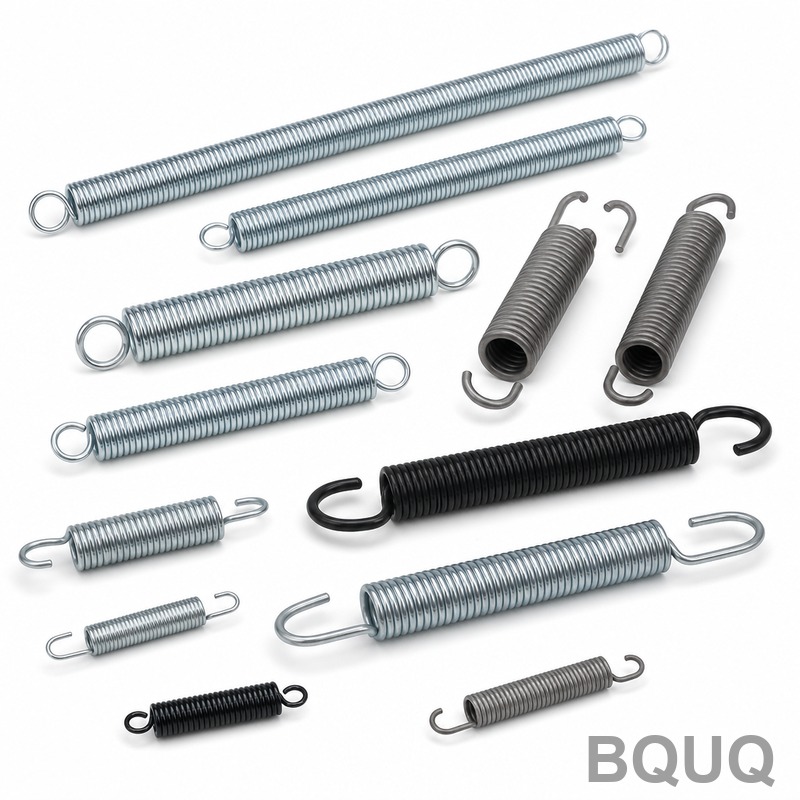
Step 5: Manufacturing Process and Lead Time
Our CNC coiling machines handle wire from 0.3 mm to 12 mm diameter with a maximum OD of 150 mm. The standard process includes coiling, stress-relieving at 350°C for 30 minutes, grinding (if specified), and shot peening for dynamic applications. Shot peening increases fatigue life by 20% but adds 3 days to the lead time and $0.10 per piece at 1,000 quantity. For corrosion protection, zinc plating adds 2 days and $0.05 per piece; electro-polishing for stainless adds 3 days and $0.15 per piece.
For a prototype order of 5 pieces, the lead time is 48 hours with a setup charge of $150. For production quantities above 1,000 pieces, the lead time is 7 working days. We recommend ordering prototypes with the same wire diameter and process as production to validate the spring rate and fatigue life. Our in-house load testing machine verifies the force at three heights and provides a certificate with each batch.
FAQ-Style Tips for Common Design Errors
Why is my spring buckling even though the stress is low? The L0/D ratio exceeds 2.6. Redesign with a larger mean diameter or add a guide rod. A spring with L0 = 80 mm and D = 25 mm has L0/D = 3.2, which will buckle under compression.
What is the minimum number of active coils? We recommend at least 3 active coils. Below this, the spring rate becomes non-linear and the manufacturing tolerance is difficult to hold. For a 2 mm wire with a 12 mm mean diameter, 3 active coils give a rate of k = (79,300 * 16) / (8 * 1,728 * 3) = 30.6 N/mm, which is very stiff.
Can I use a compression spring beyond its solid height? No. Operating at solid height causes coil collision, stress spikes, and premature failure. Always maintain a 15% clearance above solid height. If your design requires a lower compressed height, select a smaller wire or a material with a higher shear modulus.
Conclusion
Designing a compression spring is a systematic process of defining the load curve, selecting material, calculating geometry, verifying stress and stability, and specifying tolerances. The most common failure points are buckling from excessive L0/D and stress exceedance from a low spring index. For a reliable design, keep the spring index between 4 and 12, keep the L0/D below 2.6, and verify the corrected shear stress against the material limit. With these calculations, you can confidently specify a spring that meets your performance and lifespan requirements.
For a complete design review or to request a quotation, our engineering team at BQUU provides a 12-hour response on all compression spring inquiries. Send your drawing or specifications to our engineering team for a free DFM analysis and cost estimate. Contact us at Email: sc@bquq.com, WhatsApp: +86 13713157787, or visit www.bquq.com.
Related Articles
- Smart Spring Inventory Management Strategies for OEMs
- Hardware spring fatigue failure analysis and life prediction technology
- In-depth analysis of technology and process in the hardware spring industry in 2026: a full-dimensional interpretation of high stress, functional integration and engineering certification


