
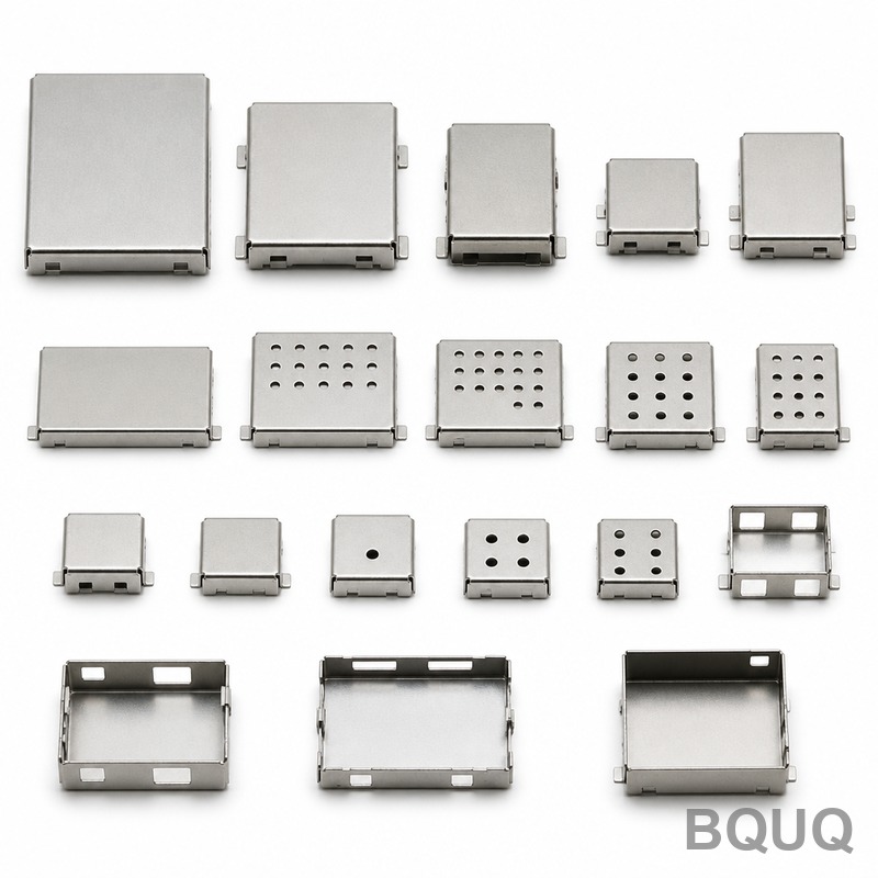
How to Design a Part for Metal Stamping: 10 DFM Rules That Cut Tooling Costs by 40%
The direct answer to how to design a part for metal stamping is to prioritize uniform wall thickness, generous bend radii, and standard hole sizes while avoiding tight tolerances below ±0.1 mm. Following these design for manufacturability (DFM) rules reduces die construction costs by 30-40% and shortens lead times from 6 weeks to 3 weeks at BQUQ's Dongguan facility. This article provides quantifiable DFM thresholds that directly impact your stamped part pricing and tooling longevity.
Material Selection and Thickness Limits
Material choice dictates stamping speed, die wear, and minimum bend radius. For carbon steel (SPCC, DC01), the recommended thickness range is 0.3 mm to 3.0 mm for progressive dies. Above 3.0 mm, you enter heavy-gauge stamping requiring slower press speeds (30-40 strokes per minute versus 60-80 SPM for thin gauge). Stainless steel (SUS304) requires 15-20% larger bend radii than carbon steel to prevent cracking. Aluminum (5052-H32) allows tighter bends but generates more galling on tool steel, increasing maintenance frequency by 25%. Specify material hardness below HRB 85 for consistent formability; harder materials above HRB 95 cause premature punch wear and require coated tooling (TiN or CrN), adding 8-12% to die cost.
| Material Type | Max Thickness (mm) | Min Bend Radius (x thickness) | Recommended Tolerance (mm) | Relative Die Cost Factor |
| Carbon Steel (SPCC) | 3.0 | 0.8 | ±0.10 | 1.00 |
| Stainless Steel (SUS304) | 2.5 | 1.2 | ±0.15 | 1.25 |
| Aluminum (5052) | 3.5 | 0.6 | ±0.12 | 1.10 |
| Copper (C1100) | 2.0 | 0.5 | ±0.10 | 1.15 |
| Brass (C2600) | 2.5 | 0.7 | ±0.10 | 1.20 |
Bend Radius and Relief Rules
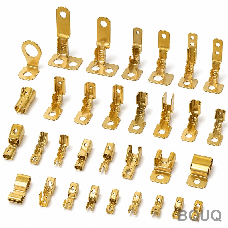
The most frequent DFM violation is specifying bend radii smaller than the material's minimum. For a 1.0 mm carbon steel part, the minimum inside bend radius is 0.8 mm (0.8 x thickness). Designing with a 0.5 mm radius forces the die maker to use a special mandrel and increases the chance of fracture by 12%. Always design bend radii equal to or greater than 1.5 times material thickness for steel, and 2.0 times for aluminum. When bending near an edge or hole, maintain a minimum distance of 3 times material thickness plus the bend radius. For example, a 1.5 mm thick part with a 2.0 mm bend radius requires 6.5 mm clearance from the bend line to the nearest hole edge. Violating this causes hole distortion and requires secondary flattening operations, adding CNY 0.15-0.30 per piece.
Hole Size, Spacing, and Wall Thickness
Punching holes smaller than 1.5 times material thickness is a common cost trap. For 1.0 mm steel, the minimum hole diameter is 1.5 mm using standard tooling. Holes below this require wire EDM punches, increasing tooling cost by CNY 3,000-5,000 per hole. The minimum distance between two hole edges must be at least 2 times material thickness, or 2.0 mm for 1.0 mm stock, whichever is greater. Hole-to-edge distance (from hole edge to part boundary) should be a minimum of 1.5 times thickness. For a 2.0 mm thick part, this means 3.0 mm from the hole edge to the part edge. Slots longer than 5 times their width require a two-stage punch to reduce tool pressure, adding 10-15% to the die cost. Design with standard punch diameters (1.5, 2.0, 2.5, 3.0, 4.0, 5.0, 6.0 mm) to avoid custom tooling premiums.
Tolerances and Surface Finish Specifications
Practical stamping tolerances depend on feature size and material thickness. For holes up to 25 mm diameter in material under 2.0 mm thick, hold ±0.10 mm. For larger features or thicker materials, relax to ±0.15 mm. Bend angle tolerances should be ±1 degree; tighter than ±0.5 degrees requires a coining operation that doubles the forming station cost. Flatness tolerance should not be tighter than 0.15 mm over 100 mm length without specifying a secondary straightening pass. Surface finish on stamped edges is naturally 3.2 to 6.3 Ra due to shear fracture; specifying better than 3.2 Ra requires a shaving operation that adds CNY 0.20-0.50 per piece. The burr height allowance should be 10% of material thickness, maximum 0.15 mm, without extra deburring cost.
Feature Complexity and Progressive Die Layout
Each additional forming station in a progressive die adds CNY 15,000-25,000 to the tooling price. A simple flat blank with holes requires 3-4 stations (pilot, punch, trim). Adding a bend requires 2 more stations. Adding a second bend in a different direction requires 3 more stations plus a part rotation mechanism. Design parts with all bends in the same direction to save 2-3 stations. The minimum web width between cuts should be 2.5 times material thickness; below this, the punch can break. For a 1.2 mm thick part, maintain 3.0 mm web width. Avoid sharp internal corners in cutouts; use a minimum radius of 0.3 mm. Sharp corners concentrate stress and require CNC wire cutting for the die insert, adding CNY 2,000 per corner versus standard milling.
Cost Breakdown and Lead Time Comparison
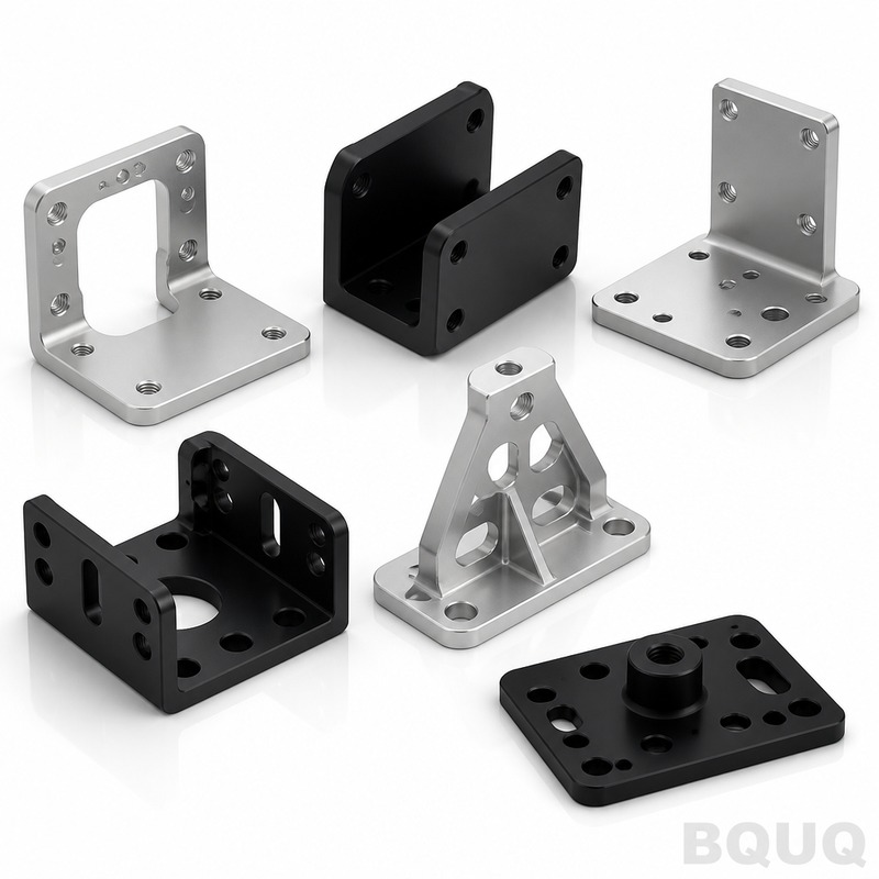
Understanding how DFM rules affect pricing enables better design decisions. At BQUQ, a simple bracket (100 mm x 50 mm x 1.5 mm steel, 4 holes, 2 bends) with compliant DFM costs CNY 35,000 for the die and CNY 1.80 per piece at 10,000 quantities. The same part with a 0.4 mm bend radius, 1.0 mm hole diameter, and ±0.05 mm tolerance costs CNY 52,000 for the die and CNY 2.60 per piece. Die lead time extends from 18 working days to 28 working days. For high-volume parts above 50,000 pieces per year, investing in a progressive die with carbide tooling (CNY 65,000) reduces per-piece cost to CNY 0.85 and achieves 150 SPM. Choosing a compound die instead of progressive saves 20% tooling cost but limits part size to 200 mm x 200 mm and increases secondary handling cost.
| Design Parameter | DFM-Compliant Design | Non-Compliant Design | Cost Impact |
| Bend radius (1.5mm steel) | 2.5 mm | 1.0 mm | +15% tooling, +20% scrap |
| Hole diameter (1.0mm steel) | 2.0 mm | 1.2 mm | +CNY 4,000 tooling |
| Tolerance on hole position | ±0.10 mm | ±0.03 mm | +25% die cost |
| Minimum web width | 3.0 mm | 1.5 mm | Punch breakage risk |
| Number of bend directions | 1 direction | 2 directions | +2 stations, +CNY 20,000 |
Practical DFM Checklist for Engineers
Before sending your drawing to a stamping supplier, verify these five rules. First, check that all bend radii are at least 1.5 times material thickness for steel and 2.0 times for aluminum. Second, confirm that all hole diameters are above 1.5 times material thickness, and spacing between holes is above 2 times thickness. Third, relax tolerances to ±0.10 mm for hole positions and ±0.15 mm for overall dimensions unless functional requirements demand otherwise. Fourth, align all bends in the same direction to minimize die stations. Fifth, add 0.3 mm minimum radius to all internal corners in cutouts. Following these rules at the design stage prevents expensive die modifications, which typically cost CNY 5,000-10,000 per change and add 5-7 working days to the schedule.
FAQ-Style Design Tips for Metal Stamping
Can I design a threaded hole in a stamped part? Yes, but use a punched pilot hole and secondary tapping, not forming threads directly. Minimum pilot hole diameter is 1.0 mm for M2 threads; tapping adds CNY 0.10 per hole. What is the maximum part size for progressive stamping? At BQUQ, progressive dies handle parts up to 400 mm x 400 mm. Larger parts require a transfer die, increasing tooling cost by 30%. How many parts should I order for cost efficiency? Tooling amortization drops significantly above 5,000 pieces. For 1,000 pieces, consider laser cutting instead; stamping becomes economical above 3,000 pieces. Can I stamp parts with 0.2 mm thickness? Yes, but below 0.3 mm, the material requires special coil handling and the press speed drops to 40 SPM, increasing per-piece cost by 40%. What is the typical press tonnage? BQUQ uses presses from 25 to 400 tons; your part's required tonnage equals cutting perimeter multiplied by material shear strength, typically 0.35 kN per mm of cut length for 1.5 mm steel.
Conclusion and Engineering Recommendation
Designing for metal stamping is a balance between functional requirements and manufacturing constraints. By adhering to the DFM rules above, you achieve tolerances of ±0.10 mm, tooling costs between CNY 30,000 and CNY 80,000, and lead times of 3-4 weeks. The most impactful single change is increasing bend radii and hole sizes to standard values, which reduces die complexity and maintenance downtime. At BQUQ, we have produced over 12,000 stamping dies in 20 years, and 90% of cost overruns trace back to non-compliant bend radii or hole spacing. Apply these rules during your design review, and you will save 15-25% on unit price and 30% on tooling investment.
For a professional DFM review of your stamped part, BQUQ provides a 12-hour quoting service. Send your 2D drawing or 3D model to our engineering team for an immediate manufacturability assessment and cost breakdown. Email: sc@bquq.com, WhatsApp: +86 13713157787, www.bquq.com.
Related Articles
- Precision Metal Stamping: Tolerances, Materials, and Design Rules
- Springback Compensation in Metal Stamping: Design & Simulation Guide
- custom stamped metal power contact spring battery clip factory
Frequently Asked Questions
What is the minimum bend radius for 1.0 mm carbon steel, and what happens if I specify a smaller radius?
For 1.0 mm carbon steel, the minimum inside bend radius is 0.8 mm (0.8 x thickness). Specifying a smaller radius, like 0.5 mm, forces the die maker to use a special mandrel and increases fracture risk by 12%. Always design bend radii at least 1.5 times material thickness for steel.
What is the minimum hole diameter I can punch in 1.0 mm steel without extra tooling costs?
The minimum hole diameter for 1.0 mm steel using standard tooling is 1.5 mm (1.5 times material thickness). Holes smaller than this require wire EDM punches, adding CNY 3,000-5,000 per hole to tooling costs. Also, maintain at least 2.0 mm between hole edges and 1.5 mm from hole edge to part boundary.
How does material choice affect die cost and bend radius requirements?
Stainless steel (SUS304) requires 15-20% larger bend radii than carbon steel to prevent cracking, with a relative die cost factor of 1.25. Aluminum (5052) allows tighter bends but increases tool maintenance by 25% due to galling. Carbon steel (SPCC) has the lowest die cost factor at 1.00 and tolerances of ±0.10 mm.
What clearance is needed when bending near a hole to avoid distortion?
Maintain a minimum distance of 3 times material thickness plus the bend radius from the bend line to the nearest hole edge. For a 1.5 mm thick part with a 2.0 mm bend radius, this requires 6.5 mm clearance. Violating this causes hole distortion and requires secondary flattening, adding CNY 0.15-0.30 per piece.


