
How to Design Parts for Metal Stamping: 10 Rules for Manufacturability
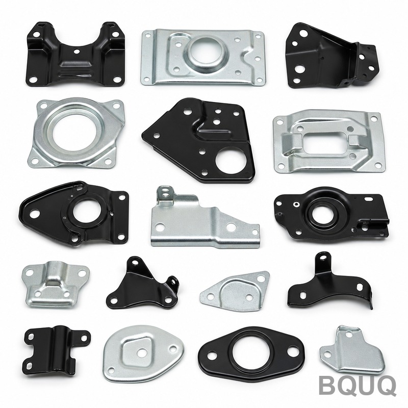
Designing parts for metal stamping is fundamentally different from designing for machining or 3D printing. The direct answer is that you must design for a process that uses hard tooling to cut and form sheet metal in high volumes, which means your part geometry must accommodate constant material thickness, specific bend radii, and draft angles. Following 10 core design rules—covering material selection, bend allowances, hole placement, and tolerance budgeting—will reduce tooling costs by up to 30% and prevent production delays. Below are the engineering rules that BQUQ applies daily in our Dongguan factory to ensure your stamped parts are cost-effective and defect-free.
What Is the First Rule About Material Selection and Thickness?
The first rule is to specify a standard material grade and thickness that is readily available in coil form, such as DC01 cold-rolled steel, 5052 aluminum, or 304 stainless steel. For metal stamping, the material thickness directly dictates the minimum bend radius, hole size, and feature spacing; for example, a 1.5 mm thick steel sheet requires a minimum bend radius of 1.0 mm to avoid cracking. Additionally, avoid specifying exotic alloys or non-standard gauges (e.g., 1.37 mm) because this forces the factory to source special coils, increasing lead time by 2-3 weeks and adding a 15-20% material surcharge. Always check the available thickness range: progressive die stamping typically handles 0.1 mm to 6.0 mm, while thicker plates above 6.0 mm are better suited for stamping with a hydraulic press or switching to CNC machining.
How Tight Can Your Tolerances Realistically Be?
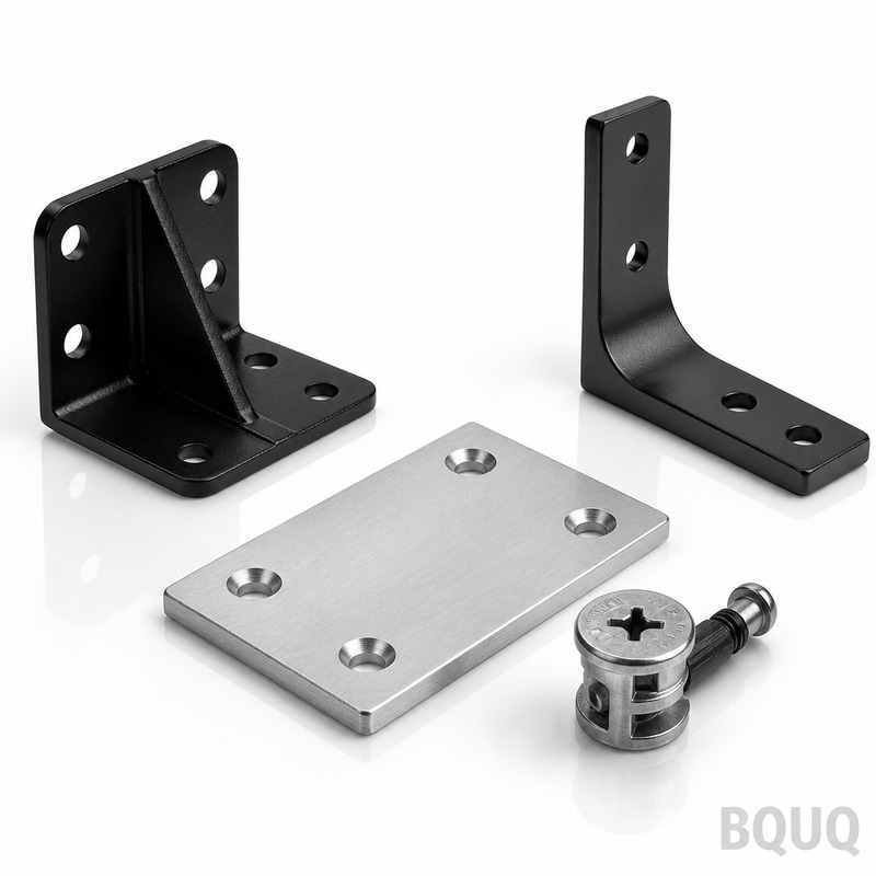
The second rule is to assign tolerances based on the stamping process capability, not on ideal machining standards. A standard metal stamping tolerance is ±0.1 mm for hole diameters and feature positions, while a precision stamping process can hold ±0.05 mm but only with added cost for tooling maintenance and in-process inspection. The table below shows the achievable tolerances relative to material thickness:
| Feature Type | Standard Tolerance (mm) | Precision Tolerance (mm) | Minimum Feature Size |
| Hole diameter (≤ 3mm thick) | ±0.10 | ±0.05 | 1.5x material thickness |
| Hole-to-hole center distance | ±0.15 | ±0.08 | N/A |
| Bend angle (90° nominal) | ±1 degree | ±0.5 degree | N/A |
| Flatness (per 100mm length) | 0.30 | 0.15 | N/A |
| Cut edge burr height | 0.10 max | 0.05 max | N/A |
If your design requires a tolerance tighter than ±0.05 mm, you must specify a secondary operation like coining or pinning, which adds USD 0.02–0.05 per part. For most automotive and electronics enclosures, a standard tolerance of ±0.10 mm is sufficient and keeps the die cost at a base level of USD 5,000–15,000 rather than USD 20,000–40,000 for precision dies.
Which Bend Radius and Forming Rules Prevent Cracking?
The third rule is that the inside bend radius must be at least 1x to 2x the material thickness, depending on the material's ductility. For aluminum 5052, the minimum inside radius is 1.5x thickness; for mild steel, it is 0.8x; for spring-tempered materials, it can be 3x. If you design a sharp 90-degree bend with a radius of zero, the die will either crack the part or require a costly coining operation to compress the material. Additionally, ensure that the bend line is not parallel to the material rolling direction whenever possible, as bending parallel to the grain increases the risk of fracture by 40%. For tall flanges, the rule is that the flange height must be at least 4x the material thickness plus the bend radius; otherwise, the part will not strip cleanly from the die.
Why Is Hole Placement Critical for Die Strength?
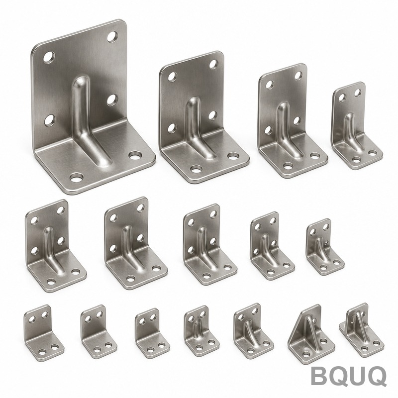
The fourth rule is to place holes and slots at least 2x the material thickness away from any bend line and at least 1.5x the material thickness away from any edge. Placing a hole too close to a bend line causes the hole to distort into an oval shape during forming, and it also weakens the die punch, which can break during high-volume production. For a 2.0 mm thick part, a 4.0 mm diameter hole must be at least 4.0 mm away from the bend tangent line. Furthermore, when designing multiple holes, the distance between hole edges should be at least 2x the material thickness; for example, two 5 mm holes in 1.5 mm steel need a 3 mm web between them to prevent the die from tearing. If your web width is too narrow, consider combining the holes into a single slot to increase die strength.
When Should You Add Relief Notches and Avoid Sharp Corners?
The fifth rule is to add relief notches at the junction of two bends or at the corner of a bent flange to prevent tearing. For example, when forming a U-channel, the bottom corners must have a relief cutout that is at least 1.5 mm wide and extends beyond the bend radius; otherwise, the material will tear at the corner during forming. Similarly, all internal sharp corners in the flat blank should have a minimum radius of 0.5 mm, but ideally 1.0 mm, to avoid stress concentrations and premature die wear. A sharp internal corner (0 mm radius) requires the die maker to use a fragile sharp punch, which will chip after 10,000–20,000 strokes, leading to downtime. In high-volume production of 500,000 parts per year, adding a 1.0 mm radius to all corners increases tooling life from 200,000 strokes to over 1,000,000 strokes.
How Does Part Size and Complexity Affect Tooling Cost and Lead Time?
The sixth rule is that tooling cost scales with the number of stations and the overall die size, not just the part size. A simple flat washer with one hole costs about USD 3,000 for tooling and takes 10 business days; a complex bracket with 5 bends, 8 holes, and a louver requires a progressive die with 12–15 stations, costing USD 25,000–50,000 with a 6–8 week lead time. The practical limit for a progressive die is a strip width of 250 mm and a feed length of 300 mm; parts larger than this require a transfer die or a compound die with slower cycle times. Furthermore, the part's annual volume dictates the die material: for volumes under 100,000 parts, use hardened tool steel (SKD11) to save cost; for volumes over 1 million, use powder metallurgy steel (e.g., ASP23) which costs 30% more but lasts 3x longer. To minimize cost, always design the part to fit within a 150 mm x 150 mm envelope if possible, as this allows the use of a standard 200-ton press and reduces the hourly press rate from USD 65 to USD 40.
Why Should You Design for the Rolling Direction and Grain Structure?
The seventh rule is to consider the anisotropic properties of the sheet metal, which means the material is stronger in the rolling direction than across it. For parts that require extreme bending without cracking, such as hinges or clips, you must specify the bend line orientation relative to the grain; the optimal orientation is with the bend line perpendicular to the rolling direction. The yield strength difference can be 10-15% between directions, and the elongation at break can drop from 30% to 20% when bending parallel to the grain. In practice, you can avoid specifying the grain direction on the drawing, which gives the factory flexibility to nest parts optimally on the strip, reducing material waste by up to 8%. However, for safety-critical parts like seat belt brackets, add a note "grain direction must be perpendicular to the primary bend axis" to ensure consistent mechanical properties.
How Much Does Tooling Cost for a Typical Stamped Part?
The eighth rule is to budget tooling cost based on the number of forming operations, not the number of holes. Each bend operation requires a separate station in the die, and each station adds approximately USD 1,500–3,000 to the tooling cost. For a typical part with 2 bends and 4 holes, the die cost is around USD 8,000–12,000, and the piece price is USD 0.15–0.30 for 1.5 mm steel in quantities of 50,000. The table below compares typical tooling and piece prices for different part complexities:
| Part Complexity | Example | Tooling Cost (USD) | Lead Time (weeks) | Piece Price (100k pcs) |
| Simple flat part | Washer, shim | 3,000 | 2 | 0.05 |
| Moderate form (2-3 bends) | Bracket, clip | 10,000 | 4 | 0.15 |
| Complex progressive die (5+ bends, 10+ holes) | Chassis, connector shell | 35,000 | 8 | 0.45 |
| High-precision (0.02mm tolerance) | Electronics shield | 50,000 | 10 | 0.80 |
To reduce tooling cost, rule nine is to consolidate features: use louvered slots instead of separate holes and forms, and avoid multiple coining operations. Additionally, rule ten is to maintain a constant material thickness across the entire part; do not design features that require thinning or thickening the sheet, as this is not possible in standard stamping.
What Are the Most Common Design Mistakes to Avoid?
The most common mistakes include designing holes smaller than the material thickness, specifying tolerances tighter than ±0.05 mm unnecessarily, and forgetting to add a bend relief notch. Another frequent error is designing a part with a sharp internal corner, which forces the toolmaker to use a weak punch that breaks frequently. Finally, avoid designing parts that require multiple separate stampings where a single progressive die could produce the part as one piece with a carrier strip; this reduces handling costs and improves positional accuracy between features.
FAQ Section
What Is the Minimum Hole Diameter for a Given Material Thickness?
The minimum hole diameter is generally 1.5 times the material thickness for standard punch-and-die setups. For example, in 2.0 mm thick steel, the smallest hole you can reliably punch is 3.0 mm in diameter without excessive punch breakage.
Can You Stamp Parts with Threads or Inserts?
Yes, you can add threads using a secondary operation called tapping, or you can install PEM inserts using a separate press operation. However, both are secondary processes that add USD 0.03–0.10 per part and require extra handling time; for low volumes, it is often cheaper to use self-tapping screws directly into the stamped hole.
How Do I Decide Between Progressive Die and Transfer Stamping?
Use a progressive die when the part is smaller than 300 mm in length and has features on a single strip that can be carried through the die. Use transfer stamping for larger parts or parts requiring deep draws, where the blank is cut and then transferred between stations by fingers; this is slower but allows more complex 3D forms.
When Should I Specify Stainless Steel Instead of Cold-Rolled Steel?
Specify stainless steel (304 or 430) when the part requires corrosion resistance, high-temperature tolerance, or a specific aesthetic finish. Be aware that 304 stainless steel work-hardens rapidly, so the minimum bend radius must be increased to 2x the material thickness, and tooling wear is 50% higher than with mild steel.
Is a Draft Angle Required on Stamped Parts?
Draft angles are not required for standard blanking and bending operations because the punch exits the material vertically. However, if you are using a deep drawing process to create a cup or pan shape, you need a draft angle of 1-3 degrees to allow the part to be ejected from the die without scratching.
What Is the Maximum Part Size for Metal Stamping?
The maximum practical part size for a progressive die is about 500 mm x 500 mm, limited by the press bed size and coil width. For larger parts, such as automotive body panels, you must use a transfer press or a tandem press line, which has lower cycle times and much higher tooling costs.
How Quickly Can I Get a Quote and Initial Samples?
At BQUQ, we provide initial engineering feedback within 24 hours of receiving your CAD file, and formal quotations within 48 hours. For simple parts with existing tooling, we can ship prototypes (soft tooling or 3D-printed patterns) within 5 business days, while hard tooling samples take 2-3 weeks depending on complexity.
Conclusion
Designing for metal stamping is about respecting the material's limits and the die's mechanical constraints. By following the 10 rules—standard material selection, realistic tolerances (≥0.05 mm), minimum bend radii (1x thickness), proper hole spacing (2x thickness), relief notches, and grain direction awareness—you will achieve lower piece prices and longer die life. The key is to consult with your manufacturer early in the design phase to validate the design for manufacturing (DFM), as a 30-minute review can eliminate costly tooling revisions. If you have a part ready for review, send your 2D or 3D CAD file to our engineering team for a free DFM analysis and a firm quote within 12 hours. Contact us at sc@bquq.com or via WhatsApp at +86 13713157787, and visit www.bquq.com for more case studies.


