
How to Specify Springs on Drawings: GD&T and Critical Dimensions
To specify springs correctly on engineering drawings, you must define the wire diameter, coil dimensions, free length, solid height, spring rate, and material, and then apply GD&T to control coil axis straightness, squareness of ends, and parallelism of ground surfaces. The critical dimensions are the free length, outside diameter, and spring rate, with standard tolerances of ±0.5 mm for free length and ±0.25 mm for outside diameter on compression springs. For precision applications, use GD&T callouts like straightness on the axis (0.5% of free length) and parallelism of end planes (0.5 mm) to ensure functional assembly and predictable load behavior.
What Are the Critical Dimensions for a Compression Spring Drawing?
The three most critical dimensions on a compression spring drawing are the free length (L0), the outside diameter (OD), and the wire diameter (d). These three values directly determine the spring rate (k = Gd^4 / 8D^3N), where G is the shear modulus, D is the mean coil diameter, and N is the number of active coils. Without controlling these, you cannot guarantee the load at a given deflection, which is the primary functional requirement. Additionally, you must specify the total number of coils (Nt), the solid height (Hs = Nt * d), and the direction of helix (right or left hand) for assembly compatibility.
How Should You Apply GD&T to the Spring Axis and End Planes?
The most important GD&T callouts for a spring are straightness of the spring axis and parallelism of the ground end planes. For the axis, apply a straightness tolerance of 0.5% to 1.0% of the free length, with a typical value of 1.0 mm for a 100 mm long spring, to prevent buckling during compression. For the end planes, apply a parallelism tolerance of 0.5 mm to 1.0 mm relative to a flat datum surface, ensuring even load distribution. Use a datum reference frame where the bottom ground end is Datum A, and the top end is controlled with a parallelism callout to Datum A. This prevents uneven stress concentration that leads to premature fatigue failure.
Which Spring Dimensions Require Tighter Tolerances: OD, ID, or Free Length?
The outside diameter (OD) and wire diameter require tighter tolerances than free length because they affect the spring rate and assembly fit. For wire diameter, use a tolerance of ±0.02 mm for wire under 3.0 mm, and ±0.05 mm for wire between 3.0 mm and 8.0 mm. The OD tolerance should be ±0.25 mm for general applications, but tighten to ±0.1 mm for precision springs that must fit into a bore with a narrow clearance. Free length tolerance can be looser, typically ±0.5 mm, because it can be adjusted by grinding the ends during manufacturing, but a tighter tolerance of ±0.25 mm is used when the spring operates near its solid height limit.
How Do You Specify Spring Rate and Load Tolerances on a Drawing?
Specify the spring rate (N/mm) as a nominal value with a tolerance of ±5% for standard springs and ±3% for precision springs. More importantly, specify the load at a defined working height (e.g., 50 N at 40 mm compressed length) with a tolerance of ±5% to ±10% of the nominal load. For example, a valve spring with a required load of 100 N at 30 mm height should be specified as "Load at 30 mm = 100 N ± 5 N." This is a functional test, and the manufacturer must verify it on a load tester, not just calculate it from dimensions, because minor variations in material modulus and coil spacing affect actual load.
What Surface Finish and Material Specifications Are Required?
The surface finish of the wire is critical for fatigue life, so specify a maximum surface roughness of Ra 1.6 µm for general springs and Ra 0.8 µm for high-cycle applications above 10 million cycles. For the material, specify the exact grade, such as ASTM A228 (music wire, tensile strength 2300-2500 MPa for 2.0 mm wire) or ASTM A313 (stainless steel 302, tensile strength 1200-1400 MPa). Include the shear modulus (G = 79.3 GPa for steel, 69.0 GPa for stainless steel) and the maximum operating temperature: 120°C for music wire, 200°C for chrome silicon, and 300°C for Inconel X-750. Also specify if the spring must be shot-peened (to increase fatigue strength by 20-30%) or preset (to remove initial set).
How Do You Define Coil Count, Pitch, and Solid Height for Manufacturing?
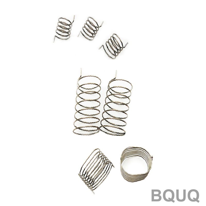
The total number of coils (Nt) and active coils (N) must be clearly stated, as they determine the pitch and solid height. The pitch (p) is calculated as (L0 - 2d) / N for compression springs with closed and ground ends, and it must be uniform to avoid load variation. Specify the solid height (Hs) with a tolerance of ±0.5 mm, and ensure the design does not allow the spring to be compressed to solid height in operation (allow at least 10-15% of free length as clearance). Include a note on the drawing stating "maximum solid height = Nt * d" so the manufacturer can verify the spring will not bind before the required deflection.
What Are the Standard Verification and Inspection Methods for Springs?
Springs are verified using three methods: dimensional measurement with calipers and micrometers, load testing with a compression tester, and metallurgical checks for hardness and surface defects. For dimensional checks, measure OD, ID, free length, and wire diameter on a sample of 5% of the batch, with a minimum of 5 pieces. Load testing is performed at 100% of the defined working height, with a gauge accuracy of ±1% of the load value. For critical springs (automotive, aerospace), perform a 100% load test and a magnetic particle inspection for surface cracks. The table below summarizes typical tolerances and test parameters for common spring specifications.
| Specification Parameter | General Tolerance | Precision Tolerance | Inspection Method |
| Wire diameter (d) | ±0.02 mm (d < 3 mm) | ±0.01 mm | Micrometer, 3-point check |
| Outside diameter (OD) | ±0.25 mm | ±0.10 mm | Caliper or optical comparator |
| Free length (L0) | ±0.50 mm | ±0.25 mm | Height gauge, vertical stand |
| Solid height (Hs) | ±0.50 mm | ±0.25 mm | Caliper, compressed state |
| Spring rate (k) | ±5% of nominal | ±3% of nominal | Load tester, slope of curve |
| Load at working height | ±5% of nominal load | ±3% of nominal load | Compression tester, 2.5 kN max |
| Axis straightness | 1.0% of L0 | 0.5% of L0 | Surface plate, dial indicator |
| End plane parallelism | 1.0 mm | 0.5 mm | Surface plate, dial indicator |
| Surface roughness | Ra 1.6 µm | Ra 0.8 µm | Profilometer |
How Do You Specify Torsion and Extension Springs Differently?
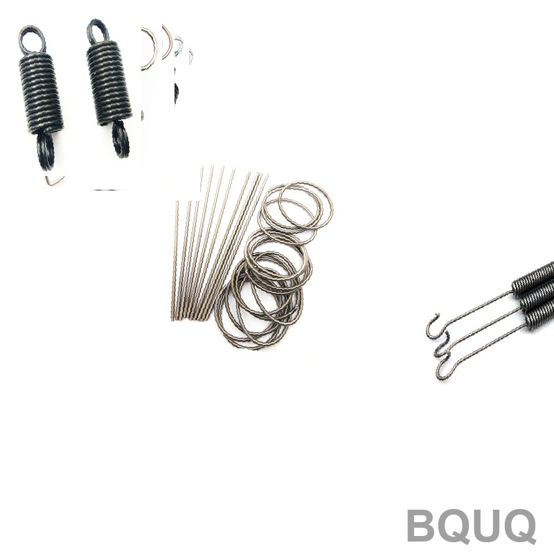
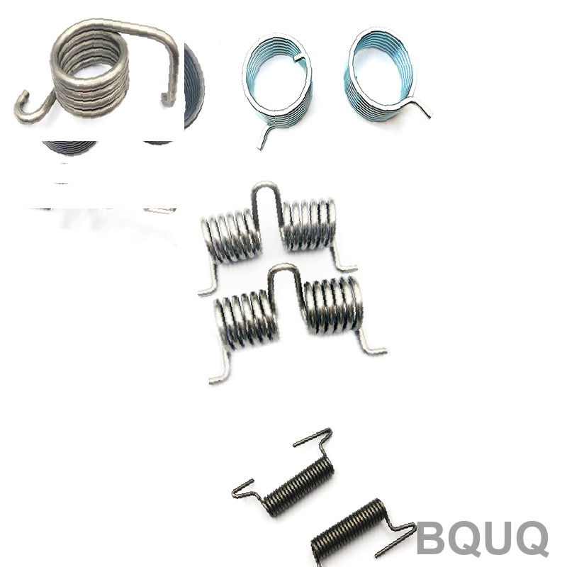
For torsion springs, the critical dimensions are the inside diameter (ID) because it mounts on a shaft, the leg angle and position, and the torque at a specified deflection angle. Specify the torque in N·mm at a given angle (e.g., 500 N·mm at 90 degrees) with a tolerance of ±5%, and control the ID with a tolerance of ±0.15 mm. For extension springs, the critical dimensions are the initial tension (force to start deflection) and the outside diameter; specify initial tension with a tolerance of ±10% of the nominal value. For both types, the GD&T callouts focus on the leg position tolerance (±1 degree for torsion) and the hook alignment (parallelism of hook planes within 1.0 mm) to ensure proper engagement in the assembly.
Can You Use GD&T to Control Spring Buckling and Stability?
Yes, you can control buckling risk by specifying a straightness tolerance on the spring axis and a maximum slenderness ratio (L0/D) of 4.0 for guided springs and 2.6 for unguided springs. Apply a straightness callout of 0.5% of free length, and add a note that the spring must be tested at full compression to verify no lateral bow exceeds 2.0 mm. For long springs (L0/D > 3.0), specify that the spring must be guided by a rod or in a bore, and reference the mating part dimensions. This is critical because buckling reduces load capacity by up to 30% and causes premature coil clash.
What Are the Common Mistakes in Spring Specifications on Drawings?
The most common mistake is specifying only the free length and OD without defining the spring rate or load at working height, forcing the manufacturer to guess the wire diameter and coil count. Another frequent error is omitting the direction of helix (right-hand vs. left-hand), which can cause assembly interference when two springs are nested. A third mistake is failing to specify the maximum operating temperature and material condition (e.g., annealed vs. hardened), leading to stress relaxation and loss of load capacity. Finally, many drawings ignore the solid height limit, causing the spring to be compressed to bind, which results in plastic deformation and failure within 1000 cycles.
FAQ Section
What Is the Standard Tolerance for Spring Free Length?
The standard tolerance for free length is ±0.5 mm for compression springs up to 200 mm long, and ±1.0 mm for springs over 200 mm. For precision springs (e.g., medical devices), tighten to ±0.25 mm. This tolerance is achievable with normal grinding and coiling processes.
How Do You Specify a Spring on a Drawing with GD&T?
Use a datum reference frame with the bottom ground end as Datum A. Apply a parallelism tolerance of 0.5 mm on the top end plane relative to Datum A, and a straightness tolerance of 0.5% of free length on the axis. Add a runout control of 1.0 mm on the OD to ensure concentricity of the coils.
What Is the Difference Between Solid Height and Free Length?
Free length is the length of the spring without any load applied, while solid height is the length when all coils are touching under full compression. Solid height equals the number of total coils multiplied by the wire diameter. The design must keep the operating deflection below 85% of the maximum travel to solid height.
Which Material Is Best for High-Temperature Spring Applications?
For temperatures up to 200°C, use chrome silicon steel (ASTM A401) because it retains 90% of its load capacity at that temperature. For temperatures up to 300°C, use Inconel X-750, which has a maximum operating temperature of 650°C but costs about 8 times more than music wire. For temperatures above 300°C, consider using a ceramic-coated spring or a belleville washer stack instead.
How Many Active Coils Should I Specify for a Compression Spring?
Specify the active coils (N) as the coils that contribute to deflection, which excludes the two end coils that are closed and ground. For a spring with a total of 8 coils, the active coils are 6. The number of active coils directly determines the spring rate, so use the formula k = Gd^4 / 8D^3N to calculate the required N for your target load.
Can a Spring Drawing Include a Load Test Requirement?
Yes, always specify a load test at the working height, such as "Test load at 40 mm compressed length = 150 N ± 7.5 N." The manufacturer will perform this test on a calibrated compression tester with a gauge accuracy of ±1% of reading. This is the only way to guarantee functional performance, as dimensional tolerances alone cannot ensure accurate load.
What Is the Minimum Order Quantity for Custom Springs?
At BQUQ, the minimum order quantity is 500 pieces for wire diameters under 3.0 mm, and 200 pieces for larger wire diameters. Prototype orders of 50 pieces are available with a lead time of 5-7 days and a tooling charge of USD 150. Production lead time is 10-15 days for quantities up to 10,000 pieces.
To ensure your spring design is manufacturable and performs correctly, always provide the load at a specific working height, not just the spring rate, and include the material grade and heat treatment. Our engineering team at BQUQ can review your drawing within 12 hours and provide a free manufacturability analysis, including suggested tolerance adjustments. For a rapid quote, email your drawing to sc@bquq.com or contact us on WhatsApp at +86 13713157787. Visit our website at www.bquq.com to download our standard spring specification template.


