
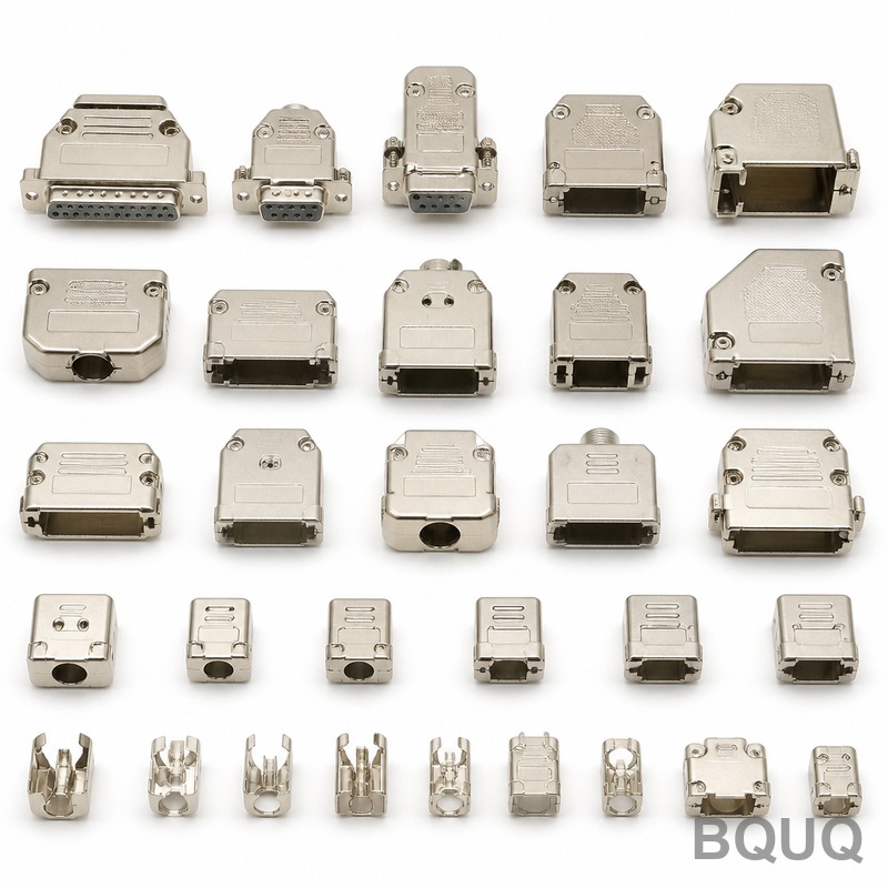
Metal Stamping Tolerance Guide: What Precision Can You Expect
Metal stamping tolerances typically range from ±0.05 mm for standard features to ±0.01 mm for high-precision progressive die operations. The exact precision you can expect depends on material thickness, part geometry, press tonnage, and die quality, with BQUQ achieving consistent repeatability of ±0.02 mm on production runs exceeding 100,000 parts. This guide provides engineering-grade data to help you specify realistic tolerances that balance cost, lead time, and functional performance.
Tolerance Classes and Industry Standards
Precision in metal stamping is governed by ISO 2768 (general tolerances) and ISO 9013 (thermal cutting, relevant for thick plates), but stamping-specific standards like VDI 2906 and DIN 6935 are more practical. For stamped parts, we categorize tolerances into three classes: standard, fine, and ultra-precision. Standard tolerances follow the "rule of thumb" for stamped parts: linear dimensions ±0.13 mm for material up to 1.5 mm thick, and ±0.25 mm for thicker materials. Fine tolerances, which require hardened tool steel dies and regular maintenance, achieve ±0.05 mm. Ultra-precision, reserved for high-volume progressive dies with carbide inserts, reaches ±0.01 mm on critical dimensions. In practice, over 80% of stamped components in automotive and electronics applications are specified to fine tolerances because they offer the best cost-performance ratio.
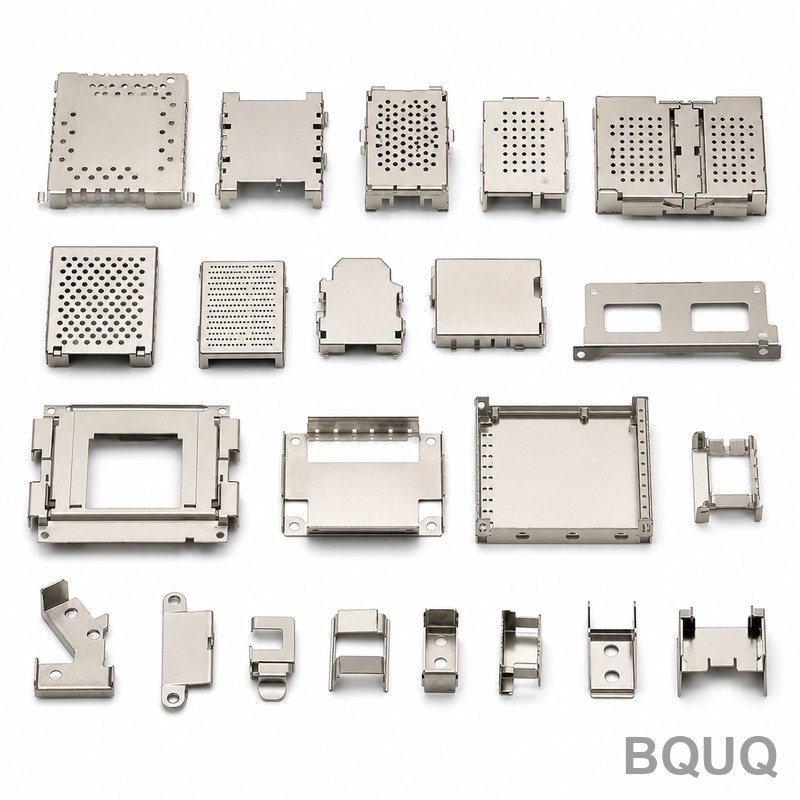
Material Thickness and Its Direct Impact on Tolerances
Material thickness is the single most influential factor in achievable stamping precision. Thinner materials (0.1 mm to 0.5 mm) allow tighter tolerances because they bend and shear more predictably, but they are prone to springback and burr formation. Thick materials (above 3.0 mm) require higher tonnage presses, and the punching clearance becomes larger, which inherently widens achievable tolerances. For example, a 0.2 mm thick stainless steel part can hold a hole-to-hole center distance of ±0.03 mm, while a 5.0 mm thick steel plate will typically hold only ±0.15 mm for the same feature. The table below shows empirical tolerance data from BQUQ production records across common materials.
| Material | Thickness Range (mm) | Standard Tolerance (mm) | Fine Tolerance (mm) | Min Hole Diameter (mm) | Burr Height Max (mm) |
| Cold Rolled Steel SPCC | 0.3 - 1.5 | ±0.13 | ±0.05 | 1.0 x thickness | 0.05 |
| Stainless Steel SUS304 | 0.2 - 2.0 | ±0.10 | ±0.04 | 1.2 x thickness | 0.04 |
| Aluminum 5052 | 0.5 - 3.0 | ±0.15 | ±0.06 | 0.8 x thickness | 0.06 |
| Brass C2680 | 0.1 - 1.0 | ±0.08 | ±0.03 | 0.7 x thickness | 0.03 |
| Copper C1100 | 0.1 - 2.0 | ±0.10 | ±0.04 | 0.9 x thickness | 0.04 |
The minimum hole diameter rule is critical: punching a hole smaller than the material thickness causes excessive punch wear and leads to breakout inconsistencies. For holes below this limit, consider laser cutting as a secondary operation, though this adds 0.5 to 1.5 RMB per hole in processing cost.
Die Design Precision and Tooling Costs
The die is the heart of stamping precision. A progressive die with multiple stations can hold tighter tolerances than a single-station die because each station performs a dedicated operation with controlled indexing. BQUQ uses CNC wire-cut dies with positioning accuracy of ±0.005 mm and surface grinding to RA 0.4 for critical surfaces. The die material also matters: D2 tool steel (hardness HRC 58-62) is standard, but for runs above 500,000 parts, we recommend carbide (HRC 78-90) which maintains edge sharpness ten times longer. Die manufacturing cost scales exponentially with precision: a standard die for a simple bracket costs 15,000 to 30,000 RMB, a fine-tolerance die costs 40,000 to 80,000 RMB, and an ultra-precision carbide die for electronics connectors exceeds 150,000 RMB. This is why tolerance specification must be driven by function, not aspiration. If a part only needs ±0.1 mm for assembly, paying for ±0.01 mm tooling is a 300% cost penalty with zero functional benefit.
Press Selection and Process Control Parameters
Press type and speed directly influence dimensional stability. Servo presses, which control ram position to ±0.01 mm, are essential for fine tolerances, especially in bending and coining operations. Mechanical presses with a flywheel deliver consistent speed but have a larger bottom-dead-center variation of ±0.05 mm, which is acceptable for standard tolerances. Stamping speed also affects precision: running at 100 strokes per minute (SPM) versus 300 SPM can change hole diameter by up to 0.02 mm due to material heating and die deflection. For aluminum and copper, which have high thermal expansion coefficients (23 ppm/°C and 17 ppm/°C respectively), we control die temperature to within ±2°C using oil coolers. Without temperature control, a 10°C rise in a 200 mm long part causes 0.046 mm of expansion, immediately pushing the part out of fine tolerance. Additionally, strip lubrication (using low-viscosity oil at 10-20 cSt) reduces friction and maintains consistent material flow, which is non-negotiable for achieving burr heights below 0.03 mm.
Dimensional Stability and Secondary Operations
Stamped parts are not always final as they leave the press. Springback, which is the elastic recovery of metal after bending, is a primary source of dimensional error. For high-strength steel (yield strength above 600 MPa), springback can reach 3 to 5 degrees on a 90-degree bend. Compensation is done by over-bending the die angle by the predicted springback amount, but this is only accurate to ±0.5 degrees in practice. For tighter angular tolerances, we use coining (a secondary pressing that locally compresses the material) which holds angles to ±0.15 degrees. Other secondary operations like deburring (vibratory finishing or electrolytic), tapping, and heat treatment (e.g., annealing at 650°C for stress relief) each introduce their own tolerance shifts. A stress-relief anneal can change flatness by 0.05 mm per 100 mm of length, so we always re-strike the part after annealing to restore flatness to ±0.03 mm. When specifying tolerances, you must account for the entire process chain, not just the stamping operation.
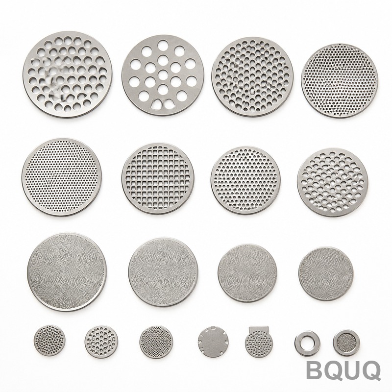
Cost vs Precision Trade-off Analysis
Precision has a clear price curve. Based on BQUQ's 2024 cost data for a typical 50 mm x 30 mm bracket in SPCC 1.0 mm thick, a standard tolerance part (±0.13 mm) costs 0.35 RMB per piece at 50,000 parts, while a fine tolerance part (±0.05 mm) costs 0.52 RMB per piece, and an ultra-precision part (±0.01 mm) costs 1.10 RMB per piece. The cost increase is driven by three factors: slower stamping speed (from 300 SPM to 80 SPM), more frequent die maintenance (every 20,000 strokes vs 100,000 strokes), and higher scrap rates (fine tolerance yields 98.5%, standard yields 99.5%). Lead time also extends: standard tolerance parts ship in 10 days, fine tolerance in 15 days, and ultra-precision in 25 days from drawing approval. For low-volume prototypes (under 1,000 parts), we recommend using soft tooling (aluminum dies) which holds ±0.10 mm and costs only 8,000 RMB, allowing you to validate form and fit before committing to production tooling.
FAQ-Style Tips for Specifying Tolerances
When you specify tolerances on a drawing, always ask yourself three questions. First, what is the functional requirement? If two holes must align with mating pins, the tolerance should be based on the smallest pin diameter and largest hole diameter, not an arbitrary round number. Second, which dimensions are critical? Mark them with a feature control frame or an "F" (for functional) symbol; non-critical dimensions can default to standard tolerances, saving cost. Third, what is the material condition? For aluminum, which is soft and prone to galling, specify a minimum bend radius of 1.5 times material thickness to avoid cracking. For stainless steel, plan for 2 times thickness. A practical rule is to never specify tighter than ±0.02 mm for any feature larger than 10 mm, because temperature variations in the factory (15°C to 35°C) alone cause more than that in dimensional change. Also, avoid stacking tolerances: if a part has a critical overall length of 100 mm composed of three segments, specify the overall length directly rather than individual segment tolerances, otherwise you will get ±0.15 mm instead of ±0.05 mm.
Conclusion and Engineering Recommendation
For most stamped parts, specifying fine tolerances (±0.05 mm linear, ±0.1 mm angular) on critical features and standard tolerances (±0.13 mm) elsewhere is the optimal engineering choice. This approach delivers functional reliability, keeps tooling costs below 60,000 RMB for most dies, and maintains production lead times under 15 days. Ultra-precision is achievable but should be reserved for high-volume electronics connectors, lead frames, and precision springs where the cost is justified by performance. Always discuss tolerance requirements with your stamping partner before finalizing the die design, as small changes in material grade or part geometry can shift achievable tolerances dramatically.
BQUUQ has manufactured precision stamped parts for 20 years, serving automotive, medical, and aerospace clients across 14 countries. Our engineering team reviews every drawing for tolerance feasibility within 12 hours of inquiry. For a free tolerance analysis and a stamped sample within 5 days, contact us at sc@bquq.com or WhatsApp +86 13713157787. Visit www.bquq.com to upload your CAD file and receive a detailed quotation with tolerance recommendations.


