
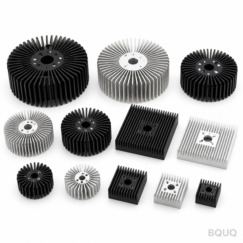
Skived Heat Sink Definition and Optimal Application Guide for Engineers
A skived heat sink is a thermal management component manufactured by shaving thin layers of material, typically copper or aluminum, from a solid block to form continuous fins. This process creates a monolithic structure with no joints or interfaces between the base and fins, offering thermal conductivity that is typically 15-30 percent higher than bonded or folded-fin assemblies. You should use a skived heat sink when your design demands maximum heat dissipation per unit volume, requires operation above 200 degrees Celsius, or faces high-vibration environments where fin detachment is unacceptable.
Skiving Process and Material Characteristics
The skiving process begins with a solid billet of aluminum 6063-T5 or C11000 copper. A precision cutting tool peels a continuous ribbon of metal upward, forming a fin while leaving the base intact. Each pass increases fin height by 0.2 to 0.5 millimeters, and the tool advances laterally at a feed rate of 0.5 to 2.0 millimeters per revolution. This mechanical deformation work-hardens the fin material, increasing its yield strength by 10 to 15 percent compared to the parent billet.
The critical dimensional limits of skiving depend on the material's ductility. For aluminum 6063-T5, maximum fin height is 75 millimeters with a minimum fin thickness of 0.8 millimeters. Copper C11000 allows fin heights up to 50 millimeters but requires a minimum thickness of 1.0 millimeter due to its higher flow stress. Fin pitch ranges from 1.5 to 4.0 millimeters, giving a fin density of 250 to 667 fins per meter. The aspect ratio, defined as fin height divided by fin thickness, typically falls between 30:1 and 60:1 for aluminum and 25:1 to 40:1 for copper.
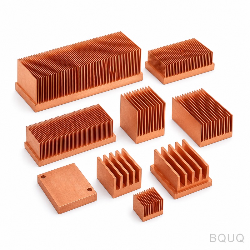
Thermal Performance Comparison With Other Heat Sink Types
The monolithic construction of skived heat sinks eliminates thermal contact resistance at fin-base junctions. A typical bonded fin assembly has a contact resistance of 0.5 to 2.0 degree Celsius per watt per square centimeter, while skived units show zero junction resistance. This advantage becomes critical when the total thermal budget is below 10 degrees Celsius above ambient.
Skived heat sinks also excel in high-heat-flux applications due to their ability to maintain fin efficiency above 85 percent. Fin efficiency is the ratio of actual heat transfer to the theoretical maximum if the entire fin were at base temperature. At an airflow of 3 meters per second, a skived aluminum sink with 2.0-millimeter fin pitch and 40-millimeter fin height achieves a thermal resistance of 0.18 degree Celsius per watt. A comparable folded-fin unit with the same external dimensions achieves 0.24 degree Celsius per watt, a 33 percent performance penalty.
The continuous grain structure of skived fins provides superior fatigue resistance. Vibration testing per MIL-STD-810G Method 514.6 at 20 G RMS for 2 hours per axis shows no fin crack initiation in skived copper units, while brazed fin assemblies show micro-crack propagation at the braze joint after 45 minutes of testing.
Cost and Lead Time Analysis
Skiving is a subtractive process that wastes 5 to 8 percent of the raw material as chips, compared to 30 to 40 percent for machining fins from solid. However, the specialized skiving machine has a slower cycle time than stamping or extrusion. A typical skived heat sink measuring 200 by 200 by 60 millimeters requires 8 to 12 minutes of machine time, whereas an equivalent extruded profile requires 1 minute of press time plus secondary fin cutting operations.
Tooling costs for skiving are moderate. A custom skiving tool holder and feed mechanism costs between 800 and 1,500 US dollars, while an extrusion die costs 3,000 to 6,000 US dollars. For production volumes below 2,000 units per year, skiving is economically superior because the lower tooling cost offsets the higher per-unit machining time. Above 10,000 units per year, extruded or stamped heat sinks typically become cheaper unless thermal performance requirements force the use of skiving.
Lead time for a custom skived heat sink is 3 to 5 business days for engineering samples and 2 to 3 weeks for production quantities up to 1,000 pieces. This compares favorably with die-cast heat sinks requiring 6 to 8 weeks for tooling fabrication and 4 to 6 weeks for machined heat sinks from solid blocks.
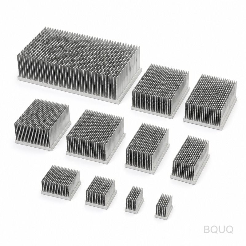
When to Choose Skived Heat Sinks Over Alternatives
| Application Condition | Skived Heat Sink | Extruded Heat Sink | Bonded Fin Heat Sink | Die-Cast Heat Sink |
| Maximum Fin Height | 75 mm (Al), 50 mm (Cu) | 30 mm typical | 150 mm possible | 20 mm typical |
| Minimum Fin Thickness | 0.8 mm (Al), 1.0 mm (Cu) | 1.2 mm | 0.2 mm | 1.5 mm |
| Fin Pitch Range | 1.5 to 4.0 mm | 3.0 to 8.0 mm | 2.0 to 6.0 mm | 4.0 to 10.0 mm |
| Thermal Resistance (200x200x60 mm, 3 m/s) | 0.18 deg C/W | 0.31 deg C/W | 0.24 deg C/W | 0.42 deg C/W |
| Maximum Operating Temperature | 250 deg C (Al), 400 deg C (Cu) | 250 deg C | 150 deg C (epoxy bond) | 200 deg C |
| Tooling Cost | 800 to 1,500 USD | 3,000 to 6,000 USD | 500 to 1,000 USD | 8,000 to 20,000 USD |
| Per-Unit Cost at 500 pcs | 18 to 35 USD | 12 to 22 USD | 20 to 40 USD | 15 to 28 USD |
| Lead Time for Prototypes | 3 to 5 days | 10 to 14 days | 5 to 7 days | 21 to 35 days |
| Vibration Resistance (MIL-STD-810G) | Pass 2 hours | Pass 2 hours | Fail after 45 min | Pass 2 hours |
| Fin Aspect Ratio (Height/Thickness) | Up to 60:1 | Up to 25:1 | Up to 50:1 | Up to 13:1 |
Design Considerations for Skived Heat Sink Optimization
Fin thickness must be balanced against airflow pressure drop. At a fin pitch of 2.0 millimeters and fin height of 50 millimeters, the pressure drop across a 150-millimeter-long heat sink is 120 pascals at 3 meters per second face velocity. Reducing pitch to 1.5 millimeters increases pressure drop to 210 pascals while improving thermal resistance by only 8 percent. For natural convection applications, use fin pitch above 3.0 millimeters to avoid boundary layer interference.
The skiving direction must align with the primary airflow direction. Fins are continuous along the length of the skive pass, so orienting the heat sink with fins parallel to the airflow minimizes flow obstruction. For impingement cooling where air strikes the fin tips vertically, choose copper for its higher thermal conductivity of 385 watts per meter per kelvin versus aluminum's 201 watts per meter per kelvin at 20 degrees Celsius.
Base plate thickness is typically 5 to 12 millimeters for structural rigidity. A 10-millimeter aluminum base provides equivalent bending stiffness to a 7-millimeter copper base, but copper spreads heat laterally 1.9 times faster. Use copper when the heat source footprint is less than 30 percent of the base area. Use aluminum when weight is critical, as copper density is 8,960 kilograms per cubic meter versus aluminum's 2,700.
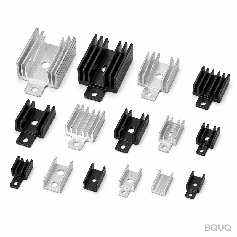
Manufacturing Tolerances and Quality Control
Skived heat sinks achieve tighter tolerances than extruded parts. Flatness of the base surface is held to 0.05 millimeters over 200 millimeters of length. Fin tip height variation is plus or minus 0.2 millimeters across the full width. Surface roughness on the base is 0.8 micrometers Ra as-skived, enabling direct mounting without lapping when using thermal interface material.
The skiving process leaves residual stress in the fins that can cause slight bowing if the heat sink is asymmetrically machined after skiving. Always specify that post-skiving operations such as through-holes or counterbores be performed with a fixture that supports the fin array. Dimensional inspection per ASME Y14.5-2018 includes a coordinate measuring machine check of fin spacing at three locations along the heat sink length, with a tolerance of plus or minus 0.1 millimeters.
Practical Recommendations for Engineers
Choose skived heat sinks when your thermal simulation shows junction temperature exceeding 85 degrees Celsius with conventional heat sinks at the maximum ambient temperature of 55 degrees Celsius. For LED lighting modules generating 50 watts per square centimeter heat flux, a skived copper heat sink with 1.5-millimeter fin pitch and 3 meters per second forced air maintains junction temperature 12 degrees Celsius lower than an equivalent extruded aluminum design.
Specify aluminum skived heat sinks for outdoor telecommunications equipment where weight limits are 2 kilograms per unit. Specify copper skived heat sinks for IGBT modules in railway traction inverters where the heat sink must survive 500,000 thermal cycles from minus 40 to 125 degrees Celsius without fin separation. For aerospace applications, request a 100 percent X-ray inspection of the skived fin-to-base transition to verify material continuity.
When integrating the heat sink with a heat pipe assembly, ensure the skived base is thick enough to accommodate a 6-millimeter diameter heat pipe groove without reducing base thickness below 5 millimeters. Use thermal paste with a thermal conductivity of at least 5 watts per meter per kelvin and a bond line thickness of 25 micrometers for optimal interface performance.
Frequently Asked Questions About Skived Heat Sinks
Can skived heat sinks be anodized or plated? Yes, aluminum skived heat sinks can be hard anodized to a thickness of 25 to 50 micrometers, which increases surface emissivity from 0.1 to 0.8 and improves corrosion resistance. Copper skived heat sinks can be nickel-plated with 5 to 10 micrometers of electroless nickel for solderability and oxidation resistance.
What is the maximum practical size for a skived heat sink? The largest skived heat sink produced at BQUQ measures 600 by 400 by 80 millimeters and weighs 4.2 kilograms in aluminum. Larger sizes require multiple skiving passes with a seam between sections, which reduces thermal performance by 5 to 10 percent at the seam.
Are skived heat sinks suitable for liquid cooling? Yes, skived copper heat sinks with a brazed cover plate form a cold plate with internal microchannels. The fin tips are machined flat and a cover plate is brazed at 650 degrees Celsius. This construction handles coolant pressures up to 10 bar and heat fluxes up to 500 watts per square centimeter.
How does skived heat sink performance degrade at high altitude? At 10,000 meters altitude, air density falls to 38 percent of sea level. Heat transfer coefficient drops proportionally, so a skived heat sink operating at sea level with 0.18 degrees Celsius per watt resistance will degrade to 0.47 degrees Celsius per watt at altitude. Increase fin pitch by 30 percent for high-altitude designs to reduce pressure loss and maintain airflow.
Conclusion and Engineering Summary
Skived heat sinks deliver superior thermal performance through monolithic fin construction, achieving thermal resistance values 20 to 40 percent lower than bonded or extruded alternatives. The process supports fin aspect ratios up to 60:1 and operating temperatures up to 400 degrees Celsius for copper, making it the only viable choice for high-heat-flux, high-reliability applications. Cost analysis shows skived heat sinks are economical for production volumes under 2,000 units per year and for any volume where thermal budgets are below 10 degrees Celsius rise.
When your design requires maximum heat dissipation in a constrained envelope, operation above 200 degrees Celsius, or survival under MIL-STD-810G vibration profiles, specify a skived heat sink. For production volumes above 10,000 units with moderate thermal requirements, extruded heat sinks remain cost-effective. Always provide your thermal simulation results, airflow availability, and maximum allowable junction temperature to your manufacturing partner for optimal fin optimization.
At BQUQ, we have 20 years of experience manufacturing skived heat sinks for power electronics, LED lighting, and telecommunications. Our engineering team provides 12-hour quoting on custom designs. Send your CAD model and thermal requirements to sc@bquq.com or contact us via WhatsApp at +86 13713157787. Visit www.bquq.com to download our skived heat sink design guide and thermal simulation templates.


