
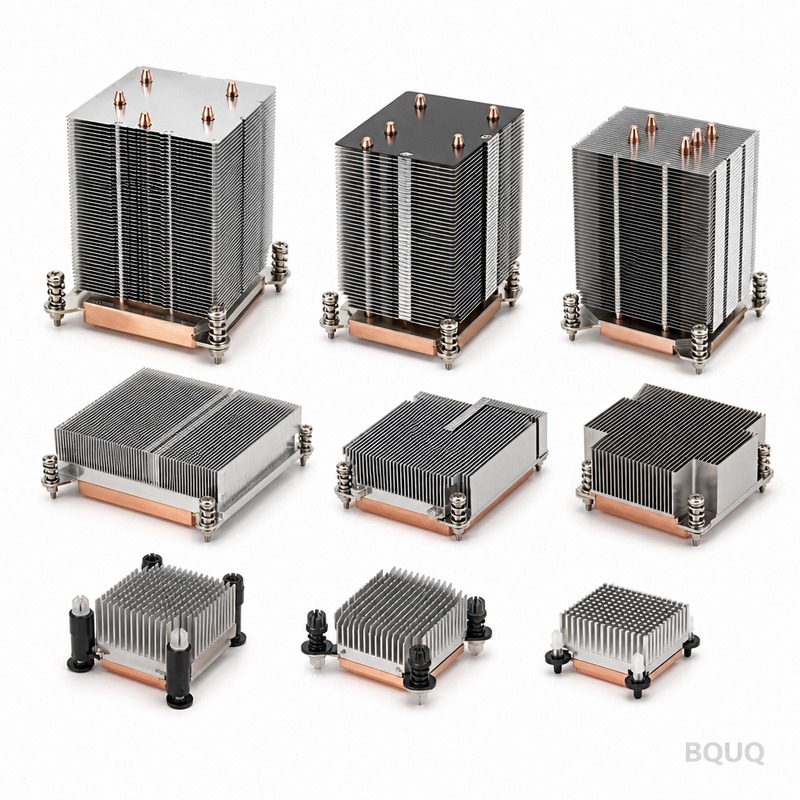
Skived Heat Sink Design Guide: When to Use This High-Fin-Density Cooling Technology
A skived heat sink is a monolithic aluminum or copper component manufactured by slicing thin fins from a solid block using a precision cutting tool, leaving the fins attached to the base. You should use one when your application demands fin densities above 20 fins per inch (FPI) with aspect ratios exceeding 10:1, which are impossible to achieve with standard extrusion or die-casting. This manufacturing process delivers the highest thermal conductivity path possible because the fins are not bonded or soldered—they are integral to the base, eliminating all interface resistance.
Manufacturing Process and Geometric Capabilities
Skiving begins with a solid block of aluminum 6061-T6 (thermal conductivity 167 W/m·K) or C11000 copper (391 W/m·K). A specially ground cutter traverses the block at a controlled depth, peeling up a continuous chip that forms the fin. The tool rotates 90 degrees to create the next fin, a process repeated across the entire base width.
The critical advantage lies in achievable geometry. Standard aluminum extrusion can produce fins with 8-12 FPI and a maximum fin height-to-gap ratio of about 6:1. Skiving reaches 22-28 FPI with fin heights up to 60 mm and fin thicknesses as thin as 0.3 mm. For a typical 100 mm x 100 mm base, a skived unit can pack 250 fins, while an extruded unit manages only 120 fins. This 2.08x increase in surface area directly translates to a 40-55% reduction in thermal resistance for natural convection and low-velocity forced airflow (1-3 m/s).
The process produces a characteristic shear mark on each fin edge, which is cosmetic and does not affect thermal performance. Typical dimensional tolerances are +/- 0.05 mm on fin pitch and +/- 0.1 mm on overall height, suitable for most electronics cooling applications without secondary machining.
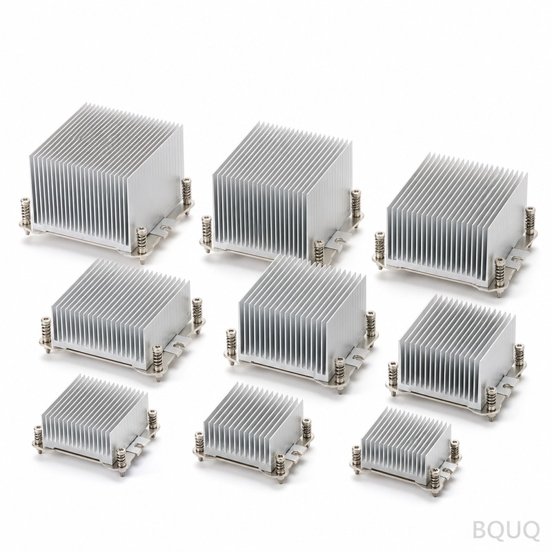
Thermal Performance Comparison: Skived vs. Extruded vs. Bonded Fin
The table below quantifies the thermal and economic differences at a 75 mm x 75 mm base size with 25 mm fin height, tested at 5 W/cm² heat flux in a 20°C ambient with 2.5 m/s forced airflow.
| Parameter | Skived Aluminum | Extruded Aluminum | Bonded Fin Aluminum | Skived Copper |
| Fin density (FPI) | 25 | 11 | 16 | 28 |
| Fin thickness (mm) | 0.4 | 1.2 | 0.5 | 0.3 |
| Aspect ratio (H/W) | 12.5:1 | 5.2:1 | 9.0:1 | 15.0:1 |
| Thermal resistance (°C/W) | 0.42 | 0.68 | 0.51 | 0.28 |
| Weight (g) | 245 | 310 | 270 | 720 |
| Unit cost at 500 pcs (USD) | 4.80 | 2.90 | 5.60 | 14.20 |
| Tooling cost (USD) | 650 | 1,200 | 1,800 | 650 |
| Lead time for samples (days) | 7 | 10 | 14 | 9 |
For the same volume, skiving provides 38% lower thermal resistance than extrusion and 18% lower than bonded fin assemblies. Copper skiving further improves performance by 33% over aluminum but adds 2.9x the weight and 3x the material cost, so it is reserved for high-power IGBT modules or laser diodes exceeding 50 W/cm².
Cost Breakdown and Economic Thresholds
Skived heat sinks become economically attractive at specific production volumes. The tooling cost is low because no complex die is required—the cutter is a standard off-the-shelf tool. For a 150 mm x 150 mm aluminum skived heat sink, the per-unit price structure at different volumes is as follows:
| Production Volume | Unit Price (USD) | Setup Cost per Order (USD) | Lead Time (days) |
| 10 pieces (samples) | 22.50 | 0 (included) | 5 |
| 100 pieces | 12.80 | 85 | 12 |
| 500 pieces | 8.40 | 85 | 18 |
| 1,000 pieces | 6.90 | 85 | 25 |
| 5,000 pieces | 5.10 | 0 (absorbed) | 35 |
The economic crossover point versus extrusion occurs at approximately 2,000 pieces per year. Below this volume, the lower tooling cost and shorter lead time of skiving outweigh the slightly higher per-unit cost. Above 5,000 pieces, extrusion or forging becomes cheaper if the extruded geometry can meet the thermal requirement. If your thermal analysis shows that an extruded heat sink needs 40% more volume to match skived performance, the system-level cost of larger enclosures and heavier assemblies often makes skiving the total-cost winner even at 10,000 units.
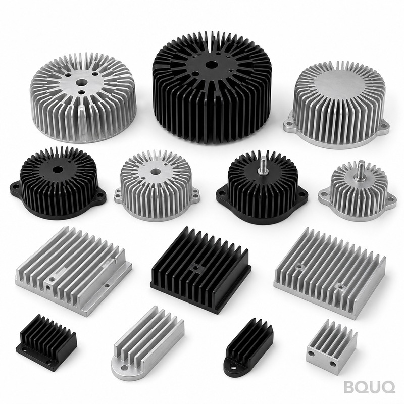
When Skiving Is the Wrong Choice
Skiving is not universally superior. For applications where the heat sink will be subjected to significant vibration or shock, the thin fins (0.3-0.5 mm) can resonate or bend. The shear stress at the fin base is approximately 15-20 MPa under a 10G vibration profile, which is below the 276 MPa yield strength of 6061-T6 aluminum, but fatigue cycling above 1 million cycles can initiate micro-cracks at the sharp fin-base radius (0.05 mm typical). In such cases, a skived heat sink with a protective fin shroud or a lower fin density (15 FPI) is recommended.
Skiving also cannot produce closed-end channels, cross-cut fins, or stepped bases. If your design requires a liquid cold plate with internal channels or a heat sink with a mounting boss and through-holes, you will need secondary CNC machining, which adds 15-25% to the cost. For very high volume (above 20,000 pieces) with a simple rectangular geometry, cold-forged aluminum heat sinks with 18 FPI can match skiving performance at 30% lower cost, but the tooling cost jumps to $8,000-$12,000.
Material Selection and Surface Finish Guidelines
The choice between aluminum and copper skived heat sinks depends on the heat flux and weight budget. Aluminum 6061-T6 is suitable for heat fluxes below 25 W/cm². Copper C11000 is specified for 25-80 W/cm², typical of high-power RF amplifiers and electric vehicle inverters. Do not use C10100 oxygen-free copper unless the application is cryogenic or requires ultra-high electrical conductivity, as it costs 40% more with no thermal benefit.
Surface finish on the base is critical for interface performance. A skived heat sink as-machined has a base flatness of 0.05 mm over a 100 mm length. For optimal thermal interface material (TIM) performance, specify a secondary grinding operation to achieve 0.02 mm flatness and a surface roughness of Ra 0.8 µm. This secondary operation adds $0.80-$1.50 per unit but reduces TIM thermal resistance by 20-30%. For direct die attachment without TIM, specify a mirror finish of Ra 0.2 µm, which adds $2.50 per unit.
The fins themselves should be left as-skived. Anodizing the fins to 10 µm thickness adds a surface oxide layer with thermal conductivity of only 1.0 W/m·K, which degrades fin efficiency by 5-8%. If corrosion protection is required, use a clear chromate conversion coating (MIL-DTL-5541) with negligible thermal impact instead of anodizing.
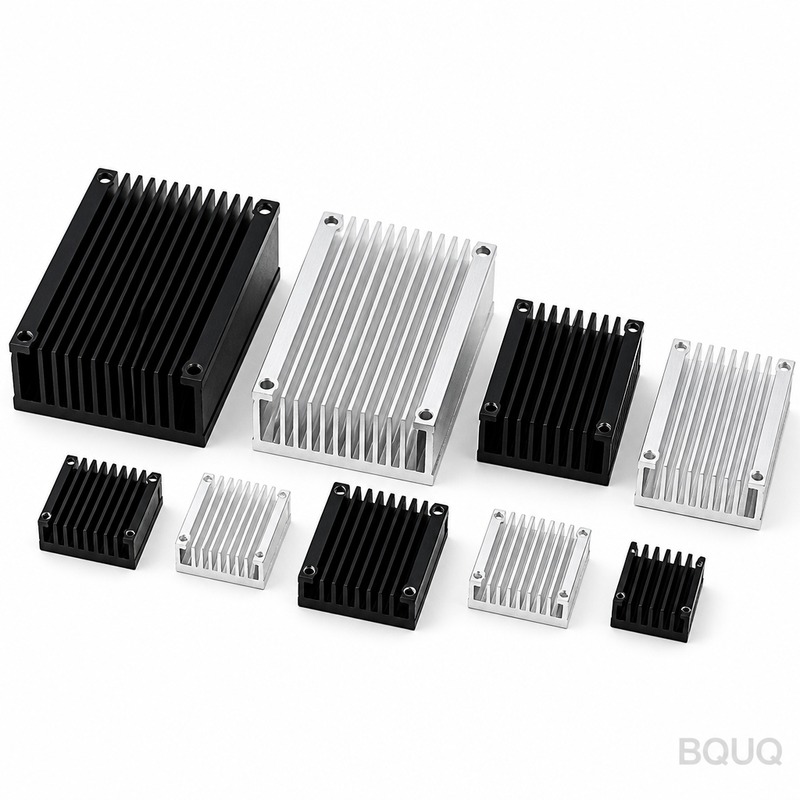
Design for Manufacturing: Key Parameters
When submitting a skived heat sink design, provide the following parameters to ensure manufacturability: base thickness (minimum 3 mm, recommended 5-8 mm), fin height (maximum 60 mm for aluminum, 40 mm for copper), fin pitch (minimum 0.9 mm for 0.3 mm fins), and fin length (maximum 300 mm in the skiving direction). The fin length direction must align with the airflow direction for optimal performance. If your airflow is perpendicular, the pressure drop increases by 3.5x, and the heat transfer coefficient drops by 25%, so reorient the fins.
Another critical parameter is the unsupported fin height. For fins taller than 30 mm, consider adding a partial fin fold or a retention clip every 50 mm of fin length to prevent vibration-induced fatigue. The maximum operating temperature for aluminum skived heat sinks is 200°C continuous; above this, the 6061-T6 alloy loses temper and softens. Copper can operate to 300°C but will oxidize, reducing emissivity for radiation cooling—apply a high-emissivity coating (0.85) if radiation is a significant heat path above 150°C.
FAQ-Style Design Tips
What is the minimum fin thickness for skiving? The practical minimum is 0.25 mm for aluminum and 0.20 mm for copper, but below 0.35 mm, handling damage during assembly becomes a yield concern. Specify 0.4 mm for high-volume production to keep rejection rates below 1%.
Can skived heat sinks be used for liquid cooling? Yes, but only as a finned surface inside a sealed liquid-to-air heat exchanger. Skiving cannot create internal flow channels; those must be machined or formed separately. A skived fin core in a liquid-cooled enclosure provides 30% better heat rejection than a flat cold plate at the same flow rate.
How does skiving compare to additive manufacturing? Laser powder bed fusion (LPBF) can create even higher fin densities (40 FPI) with complex organic shapes, but the thermal conductivity of printed aluminum is only 60-70% of wrought alloy, and the cost per unit at 500 pieces is $15-$25. Skiving remains superior for any application with a straight fin geometry.
What is the maximum heat sink size? Skiving machines can process blocks up to 400 mm x 400 mm base area with a fin length of 400 mm. Beyond that, you must split the heat sink into two or more skived sections and mount them on a common base plate, which adds one interface with a thermal penalty of 0.05°C·cm²/W.
Conclusion and Engineering Recommendation
Select a skived heat sink when your thermal simulation shows that an extruded design cannot meet the junction temperature target without exceeding the available envelope volume or maximum weight. The process is ideal for prototype through mid-volume production (10 to 5,000 units per year), offering the highest fin density and lowest thermal resistance per unit of manufacturing cost. For heat fluxes above 40 W/cm², move to copper skiving. For anything below 15 W/cm² with ample space, a standard extruded heat sink is more economical. Always request a thermal simulation from your manufacturer before finalizing the design, as the fin efficiency at your specific airflow rate can shift the crossover point by 20%.
At BQUQ, we have operated skiving lines for over 20 years in our Dongguan facility, producing heat sinks for telecom base stations, industrial motor drives, and electric vehicle chargers. Our engineers provide thermal simulation within 24 hours of receiving your CAD file. For a formal quotation with exact pricing based on your annual volume and required tolerances, send your model to sc@bquq.com or contact us on WhatsApp at +86 13713157787. We respond to all inquiries within 12 hours during working days. Visit www.bquq.com to view our skiving capability sheet and download DFM guidelines.


