
Spring Design Calculations: Engineering Reference Guide for Precision Manufacturing
The definitive answer to spring design calculations is that they require simultaneous solving of geometric, material, and load constraints using core formulas for spring rate, stress, and deflection, with iterative validation against manufacturing tolerances. This guide provides the essential equations, material data, and practical limits for compression, extension, and torsion springs, based on 20 years of CNC and spring manufacturing experience. All calculations must be verified with the specific wire diameter, mean coil diameter, and material tensile strength before production.
Spring Rate and Deflection Fundamentals
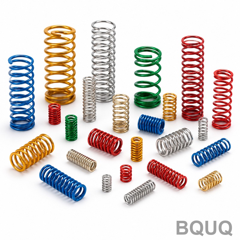
The spring rate (k) is the primary design parameter, defined as load per unit deflection. For a helical compression spring, the rate is calculated using the Wahl-corrected formula:
k = (G × d^4) / (8 × D^3 × Na)
Where G is the shear modulus of the material (79.3 GPa for music wire, 77.2 GPa for stainless steel 302), d is the wire diameter in mm, D is the mean coil diameter in mm, and Na is the number of active coils. The total deflection (δ) under load F is simply F/k. For a typical automotive valve spring with d=4.0 mm, D=28 mm, Na=6, and G=79.3 GPa, the rate calculates to 43.2 N/mm. This means a 300 N load produces 6.94 mm deflection. Always design for a maximum deflection that does not exceed 85% of the solid height to prevent coil binding and premature fatigue failure.
Material Selection and Stress Limits
Material choice dictates the maximum allowable stress and operational temperature range. The corrected shear stress (τ) at the inner fiber is calculated using the Wahl factor (Kw) to account for curvature and direct shear:
τ = Kw × (8 × F × D) / (π × d^3)
For dynamic applications, the allowable stress should not exceed 30-35% of the ultimate tensile strength (UTS). For static or infrequent loading, 45-50% of UTS is acceptable. Music wire (ASTM A228) offers the highest tensile strength (up to 2300 MPa for 1.0 mm wire) but is limited to 120°C continuous service. Stainless steel 302 (ASTM A313) handles up to 290°C but has 15-20% lower strength. Chrome silicon (ASTM A401) provides excellent fatigue life and operates to 250°C. For high-temperature environments above 300°C, Inconel X-750 or 17-7 PH stainless steel is required, though costs increase by 300-500% over music wire.
Compression Spring Design Calculations
Compression springs require careful attention to buckling, end conditions, and solid height. The slenderness ratio (L0/D) must be below 2.6 for unguided springs to avoid lateral buckling. The free length (L0) is calculated as:
L0 = (Na + 2) × d + δmax
For a spring with Na=8, d=2.5 mm, and δmax=20 mm, the free length is 45 mm. The solid height (Ls) equals (Na + 2) × d, which is 25 mm, leaving a 20 mm deflection range. The pitch (p) is determined by p = (L0 - Ls) / Na + d, giving 5.0 mm in this example. Manufacturing tolerance on free length is typically ±1.5% or ±0.5 mm, whichever is greater. The spring index (C = D/d) should be between 4 and 12; values below 4 cause excessive stress concentration, while values above 12 risk tangling and inconsistent coiling.
Extension and Torsion Spring Design
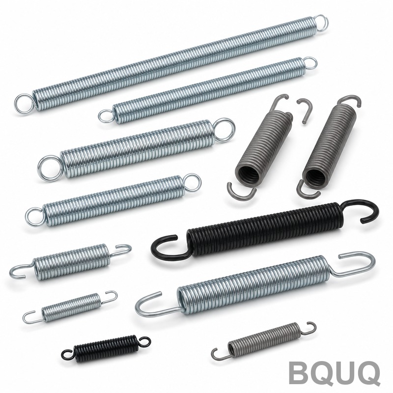
Extension springs are calculated with preload in mind. The initial tension (Pi) ranges from 10-15% of the maximum load for close-wound springs. The spring rate calculation remains identical to compression, but the total deflection includes the initial tension deflection. For a spring with k=10 N/mm and Pi=15 N, the load at 25 mm deflection is 265 N. The hook stress concentration factor is 1.5-2.0 times the body stress, so hooks must be designed with larger radii to prevent failure. Torsion springs use a different rate formula:
k_t = (E × d^4) / (10.8 × D × Na)
Where E is the elastic modulus (206 GPa for steel). The bending stress is calculated as σ = (32 × M) / (π × d^3) × Kb, where Kb is a curvature correction factor. Torsion springs are typically designed for a maximum angular deflection of 90-120 degrees per active coil. The inside diameter of a torsion spring decreases during deflection by approximately 0.1% per degree of wind-up, which must be accounted for when fitting over a mandrel or shaft.
Surface Treatment and Environmental Factors
Surface condition directly impacts fatigue life. Shot peening can increase fatigue strength by 20-30% by introducing compressive residual stresses. The recommended shot peening intensity for wire diameters 1.0-6.0 mm is 0.15-0.35 mm Almen A. Presetting (also called scragging) is a manufacturing process that sets the spring to solid height once, creating beneficial residual stresses and increasing load capacity by 10-15%. For corrosion resistance, zinc plating (8-12 μm thickness) is standard for indoor applications, while powder coating (60-80 μm) is used for outdoor exposure. Electroless nickel plating (25-50 μm) provides superior wear resistance and operates to 400°C. The operational temperature derating is critical: music wire loses 5% of its rated load capacity for every 25°C above 80°C.
Manufacturing Tolerances and Cost Data
Precision spring manufacturing requires realistic tolerance specifications. The table below shows typical achievable tolerances and relative costs for common spring materials.
| Parameter | Precision Grade | Commercial Grade | Relative Cost Factor |
| Wire diameter (mm) | ±0.01 mm | ±0.03 mm | 1.0 to 1.3 |
| Free length (mm) | ±0.5 mm | ±1.5 mm | 1.1 to 1.4 |
| Spring rate (N/mm) | ±5% | ±10% | 1.2 to 1.6 |
| Solid height (mm) | ±0.3 mm | ±0.8 mm | 1.1 to 1.5 |
| Total coils | ±0.25 coil | ±0.5 coil | 1.0 to 1.2 |
| Music wire 2.0 mm | 1800 MPa UTS | 1700 MPa UTS | 1.0 baseline |
| Stainless 302 2.0 mm | 1450 MPa UTS | 1350 MPa UTS | 1.8 to 2.2 |
| Chrome silicon 2.0 mm | 1650 MPa UTS | 1550 MPa UTS | 2.0 to 2.5 |
| Inconel X-750 2.0 mm | 1200 MPa UTS | 1100 MPa UTS | 4.0 to 5.0 |
Lead times for custom springs range from 3-5 working days for prototypes (1-100 pieces) to 10-15 working days for production runs (1000+ pieces). Tooling costs are minimal for springs under 10 mm wire diameter, typically 100-300 USD. Minimum order quantities start at 500 pieces for commercial grade, but precision grade can be ordered in quantities of 50 pieces at a 30-40% unit price premium.
Practical Design Recommendations
Always specify the operating temperature range and maximum deflection in your drawing, not just the free length and wire diameter. Provide the load at two specific heights (e.g., 50 N at 20 mm, 100 N at 35 mm) rather than only a spring rate, as this ensures the manufacturer can validate the correct wire tension. For critical fatigue applications, request a proof test of 100% of springs to 105% of maximum operating load. Design with a spring index between 6 and 9 for optimal manufacturability and cost. If your calculated stress exceeds 40% of UTS for dynamic loading, increase the wire diameter or use a higher-grade material rather than adding more coils, which increases solid height and potential buckling. Always include a tolerance on the direction of coil winding (left or right hand) if the spring interacts with threaded components. For high-volume production, verify that your design allows for the use of continuous coiling machines, which require a minimum of 3 mm wire diameter for optimal feeding speeds.
This engineering reference guide provides the essential calculations and data for successful spring design. Proper application of these formulas, combined with realistic tolerance specifications and material selection, ensures functional and cost-effective springs. For complex geometries or unusual load requirements, consult with the manufacturer during the design phase to avoid costly revisions.
BQUU offers precision spring manufacturing with 20 years of experience in CNC machining and metal forming. Our engineers provide free design validation and material recommendations. Send your drawings for a 12-hour quotation. Email: sc@bquq.com, WhatsApp: +86 13713157787, www.bquq.com.


