
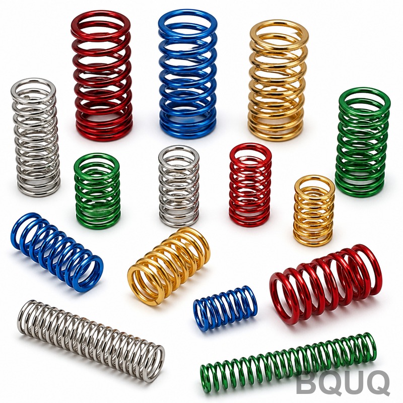
Spring Design Calculations: Engineering Reference Guide for Precision Manufacturing
The direct answer to the question of how to calculate spring design parameters is that you must balance four interdependent variables: spring rate (k), shear stress (τ), solid height, and fatigue life. These calculations are governed by the Wahl factor and Hooke's Law, and they require iteration because changing wire diameter affects all other parameters simultaneously. For a compression spring made of ASTM A228 music wire, a standard starting point is a spring rate of 10 N/mm with a maximum operating temperature of 121°C, but final values require verification against your specific load and deflection requirements.
Material Selection and Its Impact on Calculations
The choice of material is the first variable that determines all subsequent spring calculations because it sets the maximum allowable shear stress. For our CNC and wire-forming operations in Dongguan, we commonly process four primary spring materials, each with distinct mechanical properties that affect the calculation constants.
Music wire (ASTM A228) offers the highest tensile strength for its diameter, ranging from 2,300 MPa for 0.5 mm wire down to 1,500 MPa for 6.0 mm wire. This material is suitable for dynamic applications but has a maximum service temperature of 121°C. Stainless steel 302 (ASTM A313) provides corrosion resistance with a tensile strength of 1,800 MPa for 1.0 mm wire and operates up to 260°C. Chrome silicon (ASTM A401) delivers the best fatigue performance with a tensile strength of 1,900 MPa and a temperature ceiling of 232°C. Oil-tempered wire (ASTM A229) is the economical choice for static applications, with 1,600 MPa strength and a 149°C temperature limit.
When performing initial calculations, you must apply a correction factor to the ultimate tensile strength. For music wire, the recommended maximum design stress in static applications is 45% of tensile strength, while for dynamic applications it drops to 30-35%. These percentages directly influence the wire diameter calculation through the shear stress formula.
Core Spring Rate and Deflection Equations
The fundamental calculation for any spring design begins with the spring rate equation: k = F/d, where k is the spring rate in N/mm, F is the applied force in Newtons, and d is the deflection in millimeters. This equation is linear for springs operating within their elastic limit, but the geometric parameters must be calculated using the torsional stress formula.
The spring rate for a round wire compression spring is calculated as: k = (G × d^4) / (8 × D^3 × Na), where G is the shear modulus (79.3 GPa for steel), d is the wire diameter, D is the mean coil diameter, and Na is the number of active coils. For example, a spring with 1.5 mm wire, 12 mm mean diameter, and 10 active coils produces: k = (79,300 × 1.5^4) / (8 × 12^3 × 10) = 3.87 N/mm.
The shear stress calculation requires the Wahl factor (Kw) to account for curvature and direct shear: Kw = (4C - 1)/(4C - 4) + 0.615/C, where C is the spring index (D/d). The resulting stress is τ = Kw × (8 × F × D) / (π × d^3). For our example with a 100 N load: C = 8, Kw = 1.184, and τ = 1.184 × (8 × 100 × 12) / (π × 1.5^3) = 1,073 MPa. This stress must remain below the material's allowable limit of 45% of tensile strength.
Buckling, Solid Height, and Free Length Verification
Buckling becomes a critical calculation when the spring's free length exceeds four times its mean diameter. For a spring with Lf/D ratio greater than 4, you must verify stability using the critical buckling load formula: Fcr = k × Lf × (1 - sqrt(1 - (2.63 × D / Lf)^2)). If the applied load approaches Fcr, you need to add a guide rod or sleeve.
The solid height calculation is essential for manufacturing feasibility. For squared and ground ends, solid height equals (Nt × d), where Nt is total coils. For a spring with 12 total coils of 1.5 mm wire, solid height is 18 mm. The free length must be at least 15% greater than solid height to prevent coil binding during operation. We typically recommend a minimum clearance of 1.5 mm between coils at maximum deflection for reliable long-term performance.
The number of active coils depends on end conditions. For plain ends, active coils equal total coils. For closed and ground ends, subtract 2 from total coils. Our standard manufacturing tolerance for free length is ±1.0% or ±0.5 mm, whichever is greater, and for spring rate it is ±5% of the calculated nominal value.
Fatigue Life and Dynamic Load Calculations
For springs subjected to cyclic loading, fatigue life calculations replace simple static verification. The Modified Goodman diagram determines the allowable alternating stress based on the mean stress. For chrome silicon wire at 10^6 cycles, the endurance limit is approximately 45% of tensile strength, compared to 35% for music wire.
The calculation procedure requires determining the minimum and maximum loads, then computing the mean stress (τm) and alternating stress (τa). The fatigue failure criterion is: τa/Se + τm/Sut ≤ 1, where Se is the endurance limit and Sut is the ultimate tensile strength. For a spring with mean stress of 400 MPa and alternating stress of 150 MPa in music wire (Sut = 2,000 MPa, Se = 700 MPa): 150/700 + 400/2,000 = 0.214 + 0.200 = 0.414, which is safe.
For high-cycle applications exceeding 10^7 cycles, we recommend shot peening to increase fatigue life by 20-30%. The peening process induces compressive residual stresses on the wire surface, effectively raising the endurance limit. This process adds approximately 0.10-0.15 USD per piece for a 20 mm diameter spring in our facility.
Manufacturing Tolerances and Cost Considerations
Spring manufacturing tolerances directly impact the calculation results, and you must specify realistic values for production. Our standard CNC coiling machine achieves tolerances of ±0.05 mm on wire diameter, ±0.25 mm on free length for springs under 100 mm, and ±1.0 degree on coil angle. The spring rate tolerance is typically ±5%, but this can be tightened to ±3% with additional 100% inspection at a cost premium.
| Parameter | Music Wire A228 | Stainless 302 | Chrome Silicon | Oil Tempered A229 |
| Tensile Strength (1mm wire) | 2,300 MPa | 1,800 MPa | 1,900 MPa | 1,600 MPa |
| Max Service Temperature | 121°C | 260°C | 232°C | 149°C |
| Max Design Stress (static) | 1,035 MPa | 810 MPa | 855 MPa | 720 MPa |
| Relative Material Cost Index | 1.0 | 1.3 | 1.5 | 0.8 |
| Recommended Application | Dynamic, high strength | Corrosive environments | High fatigue life | Static, cost-sensitive |
The cost per piece for a typical compression spring (20 mm free length, 1.5 mm wire) ranges from 0.05 USD for oil-tempered wire in 10,000-piece quantities to 0.15 USD for chrome silicon with shot peening. Lead time for standard materials is 2-3 weeks, while custom alloys require 4-6 weeks. We maintain inventory of common wire sizes from 0.1 mm to 12 mm diameter to expedite sampling.
Practical Recommendations for Design Engineers
For optimal spring design, start with a target spring index between 4 and 12. Values below 4 cause high stress concentration and manufacturing difficulty, while values above 12 result in unstable springs prone to buckling. We recommend a spring index of 7-9 for most industrial applications as this balances stress distribution with manufacturing repeatability.
When calculating for elevated temperatures, reduce the shear modulus by 5% for every 50°C above ambient. Additionally, stress relaxation becomes significant above 100°C for music wire, so you must increase the design stress margin by 15% if operating continuously at 100°C. For springs exposed to moisture, apply a zinc or phosphate coating, which increases the wire diameter by 0.005-0.010 mm and must be included in your calculations.
Always specify the direction of coil winding (right-hand or left-hand) in your drawing. Right-hand is standard for compression springs, but left-hand is required when nesting multiple springs concentrically to prevent interlocking. For precision applications requiring consistent force output, we recommend specifying a load tolerance at a given height rather than a spring rate tolerance, as this is easier to verify in production.
We also advise providing the solid height and maximum allowable outside diameter in your print. These constraints often become the limiting factor in design iterations. If your calculated free length exceeds your space envelope, increasing wire diameter while reducing the number of coils can maintain the same spring rate while shortening the free length.
For prototype validation, we recommend ordering 10-20 samples across the tolerance range to verify that your calculations hold under real manufacturing conditions. Our engineering team can provide a free design review within 12 hours of receiving your sketch or CAD file, including calculations verification and material recommendations. Contact us at sc@bquq.com or WhatsApp +86 13713157787, or visit www.bquq.com to submit your spring design for a manufacturability assessment. Our 20 years of precision manufacturing experience ensures your spring calculations translate into reliable, cost-effective production parts.


