
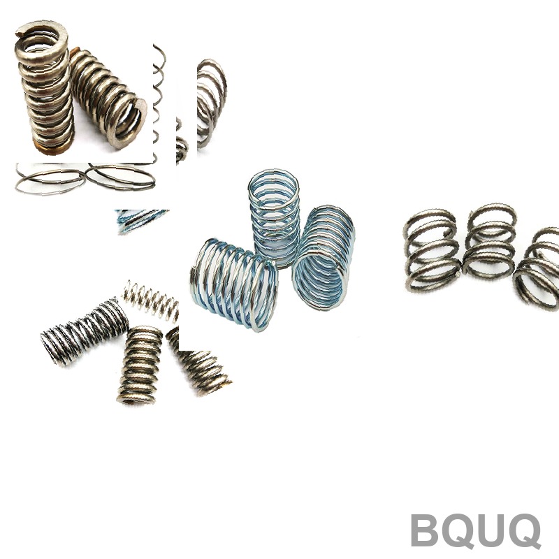
Spring Design Calculations: Engineering Reference Guide for Precision Manufacturing
Precision spring design hinges on a defined set of calculable mechanical properties, primarily stress, rate, and deflection. The direct answer is that you must verify shear stress against material yield limits using the Wahl factor, determine the spring rate via the standard coil count formula, and iterate on wire diameter and mean coil diameter to meet load-at-length specifications. This guide provides the empirical equations and real-world manufacturing data necessary to finalize a production-ready design for CNC-assisted processes.
Core Spring Design Equations and Stress Analysis
The foundation of any helical compression or extension spring calculation is the torsional stress equation modified by the Wahl factor (K_w) to account for curvature and direct shear. The design must ensure that the corrected stress (τ) remains below the material's allowable torsional yield strength, typically 45-55% of the ultimate tensile strength for music wire and chrome silicon.
The primary formulas are: - Spring Rate (k): k = (G × d^4) / (8 × D^3 × N_a) - Wahl Factor (K_w): K_w = (4C - 1)/(4C - 4) + 0.615/C - Corrected Shear Stress (τ): τ = K_w × (8 × F × D) / (π × d^3) - Deflection (δ): δ = F / k
Where: - G = Shear modulus (11.5 × 10^6 psi for steel) - d = Wire diameter (inches) - D = Mean coil diameter (inches) - C = Spring index (D/d) - N_a = Number of active coils - F = Applied load (lbf)
For a typical compression spring with a 0.5-inch mean diameter and 0.0625-inch wire, the spring index is 8.0. The Wahl factor calculates to 1.184. If the load is 20 lbf, the corrected stress is approximately 61,500 psi, which requires a material with a tensile strength above 120,000 psi to maintain a safe 50% utilization factor.
Material Selection and Temperature Limits
The material choice dictates the maximum operating temperature, corrosion resistance, and cost. For standard industrial applications below 250°F, oil-tempered chrome-vanadium or music wire is standard. For elevated temperatures above 350°F, you must switch to high-speed steel or Inconel X-750, which retains 80% of its room-temperature strength at 1000°F.
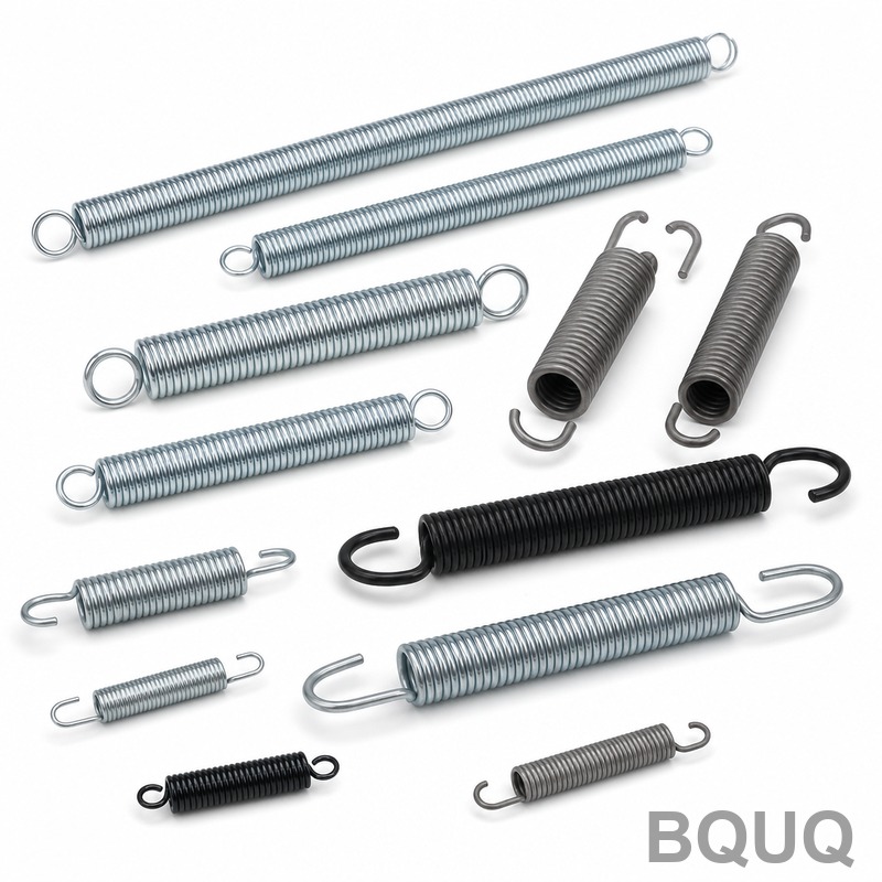
The table below compares common spring materials used in BQUQ’s production lines, including their maximum service temperature and relative cost index.
| Material | Max Temp (F) | Shear Modulus (psi) | Cost Index | Typical Tensile Strength (psi) |
| Music Wire ASTM A228 | 250 | 11.85 x 10^6 | 1.0 | 230,000 - 280,000 |
| Oil-Tempered Chrome-Vanadium | 400 | 11.5 x 10^6 | 1.3 | 200,000 - 240,000 |
| Stainless Steel 302 | 550 | 10.0 x 10^6 | 2.1 | 180,000 - 220,000 |
| Inconel X-750 | 1000 | 11.3 x 10^6 | 8.5 | 160,000 - 190,000 |
| Beryllium Copper | 400 | 6.0 x 10^6 | 6.0 | 170,000 - 200,000 |
For a heat sink clip requiring consistent force at 200°F, 302 stainless steel is preferred despite a 13% lower shear modulus compared to music wire, because the modulus reduction must be factored into the initial spring rate calculation to prevent relaxation over time.
Spring Index and Manufacturing Constraints
The spring index (C = D/d) is a critical manufacturability parameter. Industry best practice dictates a spring index between 4 and 12. An index below 4 causes excessive stress concentration and tool wear, while an index above 12 makes the spring prone to buckling and difficult to coil without distortion.
For our CNC coiling machines, the practical limits are: - Minimum wire diameter: 0.008 inches (0.2 mm) - Maximum wire diameter: 0.500 inches (12.7 mm) - Minimum spring index: 3.5 (requires special mandrels) - Maximum free length: 12 inches (300 mm) - Tolerance on free length: ±0.5% or ±0.005 inches, whichever is greater
When the spring index exceeds 10, the buckling factor becomes critical. For a compression spring with a free length 4 times the mean diameter, the slenderness ratio is 4.0. If this ratio exceeds 2.6, you must either add a guide rod or redesign with a larger wire diameter to increase the solid height and reduce the free length ratio.
Tolerance Standards and Load Precision
Precision springs require specific load tolerances at a given deflection. The standard tolerance for a spring rate is typically ±5% for general use and ±2% for precision applications. However, the load at a specific height, which is what most assemblies require, is controlled by the total number of coils and the free length.
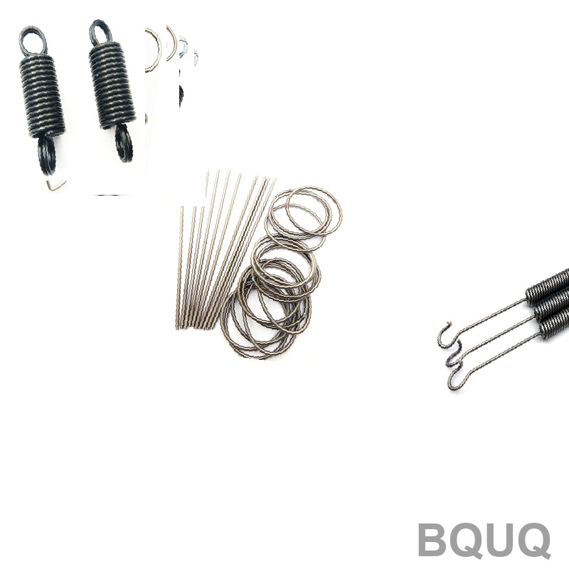
At BQUQ, we manufacture to the following internal tolerances: - Load at specified height: ±3% (standard), ±1% (precision ground ends) - Outer diameter: ±0.5% or ±0.003 inches - Free length: ±1% or ±0.010 inches - Total coils: ±0.25 coil
For critical applications like valve springs in automotive engines, the load tolerance at a 0.5-inch deflection is held to ±2%. This requires grinding both ends flat and parallel within 0.002 inches, which adds approximately 15% to the unit cost but ensures consistent performance at 6000 RPM.
Cost Drivers and Lead Time Analysis
The cost of a precision spring is driven primarily by wire material, tooling complexity, and secondary operations such as grinding or shot peening. The price per piece decreases significantly with volume, but setup time for custom springs remains fixed.
Typical pricing for a 0.0625-inch wire, 1-inch free length, 0.5-inch OD compression spring: - Prototype (1-10 pcs): $35.00 per piece - Low volume (100 pcs): $2.80 per piece - Medium volume (1000 pcs): $0.95 per piece - High volume (10,000 pcs): $0.45 per piece
The lead time for standard materials like music wire is 3-5 business days for prototypes and 2-3 weeks for production quantities. For Inconel or beryllium copper, the material procurement adds 2 weeks to the lead time. Shot peening to increase fatigue life adds 2-3 days and 10% cost, but it is essential for springs subjected to cyclic loads exceeding 100,000 cycles.
Deflection and Fatigue Life Calculations
For dynamic applications, the fatigue life is determined by the stress range (τ_max - τ_min) versus the endurance limit of the material. For unpeened music wire, the endurance limit is approximately 45,000 psi. Shot peening can raise this to 60,000 psi.
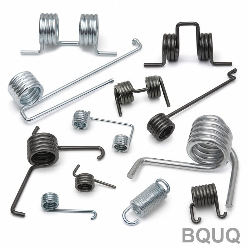
Calculate the factor of safety using the Goodman criterion: - τ_alt = (τ_max - τ_min) / 2 - τ_mean = (τ_max + τ_min) / 2 - Safety Factor = S_e / (τ_alt + (τ_mean × S_e / S_ut))
For a spring operating between 10 lbf and 30 lbf, with a mean stress of 40,000 psi and an alternating stress of 15,000 psi, the Goodman safety factor for unpeened music wire (S_e = 45,000 psi, S_ut = 240,000 psi) is 1.58. This is acceptable for 1 million cycles. For 10 million cycles, you must shot peen or reduce the maximum load to lower the alternating stress below 12,000 psi.
Practical Recommendations for Design Validation
Do not rely solely on theoretical calculations. Before committing to large production runs, validate your design with a physical prototype and a compression test fixture. Measure the spring rate over 20% to 80% deflection range; the measured rate typically varies from calculated by 3-5% due to friction and end-coil effects.
Recommendations for robust design: - Always specify the direction of the helix (right-hand is standard) for assembly clearance - For compression springs, specify closed and ground ends if the spring index is below 6 - Avoid operating a spring at its solid height; design for a 15% clearance between maximum deflection and solid height - For high-temperature applications, subtract the thermal expansion of the wire from the free length during calculation - Specify a spring index of 8-10 for optimal balance of stress and manufacturability
If your calculated stress exceeds 50% of the tensile strength, increase the wire diameter or reduce the mean diameter. A simple rule is that doubling the wire diameter reduces the stress by a factor of 8, but increases the spring rate by a factor of 16, so you must compensate by reducing the number of active coils.
Conclusion and Engineering Support
Spring design is a balance of geometric constraints, material limits, and cost. The equations provided in this guide are the industry standard for calculating rate, stress, and deflection, but the practical tolerances and manufacturing limits are equally critical. A spring that calculates perfectly on paper will fail in production if the spring index is too low or the tolerance on wire diameter is not controlled.
For your next project, send us your load requirements, available space envelope, and operating environment. Our engineers will validate your calculations, provide DFM feedback, and deliver a production quote with exact tolerances. We can provide prototype springs within 48 hours for standard materials.
Get your precision spring quote in 12 hours or less. Contact our engineering team at Email: sc@bquq.com, WhatsApp: +86 13713157787, or visit www.bquq.com for immediate assistance on your design.
Related Articles
- Where to Buy Custom Metal Springs Online: Top 7 Suppliers
- Size control and online intelligent detection technology of precision spring
- From "standard parts" to "functional parts": 2026 hardware spring industry technology trends and functional innovation engineering direction
Frequently Asked Questions
What is the Wahl factor and why is it critical in spring design?
The Wahl factor (K_w) corrects the torsional stress equation for curvature and direct shear in helical springs. It is calculated as K_w = (4C - 1)/(4C - 4) + 0.615/C, where C is the spring index (D/d). For a spring with a 0.5-inch mean diameter and 0.0625-inch wire, the index is 8.0 and K_w is 1.184. This factor ensures the corrected stress remains below the material's allowable torsional yield strength.
What materials are recommended for springs operating above 350°F?
For temperatures above 350°F, you must use high-speed steel or Inconel X-750. Inconel X-750 retains 80% of its room-temperature strength at 1000°F and has a maximum service temperature of 1000°F. Its shear modulus is 11.3 x 10^6 psi, with a cost index of 8.5 and typical tensile strength of 160,000-190,000 psi, making it suitable for high-heat applications.
How do you calculate the spring rate for a compression spring?
The spring rate (k) is calculated using the formula k = (G × d^4) / (8 × D^3 × N_a), where G is the shear modulus (11.5 x 10^6 psi for steel), d is wire diameter, D is mean coil diameter, and N_a is the number of active coils. For example, with a 0.5-inch mean diameter and 0.0625-inch wire, the spring index is 8.0, and the rate is determined by iterating on wire and coil diameters to meet load-at-length specs.
Why is 302 stainless steel preferred for heat sink clips at 200°F?
302 stainless steel is preferred for heat sink clips requiring consistent force at 200°F because it prevents relaxation over time, despite having a 13% lower shear modulus (10.0 x 10^6 psi) compared to music wire. Its maximum service temperature is 550°F, and the modulus reduction must be factored into the initial spring rate calculation to maintain force stability under sustained load.


