
Spring End Grinding Techniques and Specifications for Precision Coil Manufacturing
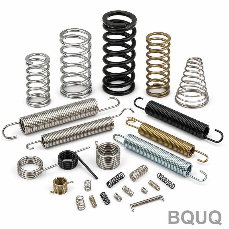
Spring end grinding is the process of removing material from the flat ends of compression springs to create a parallel, square seating surface. The direct answer to the question of how this is done is: springs are held in a rotating fixture (either a magnetic chuck or a dedicated spring grinding machine) and passed across the face of a rotating abrasive wheel, with the grinding depth controlled to achieve a specified flatness and squareness. For most industrial applications, this process achieves a flatness of 0.002 to 0.005 inches (0.05 to 0.13 mm) and a squareness of 1 to 3 degrees, depending on the spring index and wire diameter.
Fundamental Grinding Process and Machine Setup
The core operation involves two opposing grinding wheels on a dual-face grinder, or a single wheel with a magnetic rotary carrier. At BQUQ, we use both through-feed and plunge-grind methods. The through-feed method processes continuous coils of springs loaded into a vibrating bowl that aligns them into a rotating disc. The disc carries the springs between the two wheels, grinding both ends simultaneously. Plunge grinding is reserved for springs with very thin wire (below 0.5 mm) or those requiring extreme precision.
The critical machine parameters are wheel speed, feed rate, and coolant flow. Typical wheel speed is 1,800 to 3,600 RPM for conventional aluminum oxide wheels, and up to 6,000 RPM for CBN (cubic boron nitride) wheels. Feed rate for standard steel springs is 15 to 30 parts per minute on a 12-station rotary machine. Coolant, typically a water-soluble oil at 5% concentration, must be applied at 20 to 40 liters per minute to prevent heat buildup that can alter the spring's free length or create blueing on the wire surface.
Material Selection and Grindability
The grindability of a spring directly correlates with its material hardness and thermal conductivity. Music wire (ASTM A228) is the most common but is prone to burning due to its high carbon content. Chrome silicon (ASTM A401) and chrome vanadium (ASTM A231) offer better heat resistance and are easier to grind without surface cracks. Stainless steel (302 and 316) requires specialized wheels with softer bonds to avoid glazing.
For springs made from pre-hardened wire, the grinding process must remove no more than 0.010 inches (0.25 mm) per pass. Exceeding this causes localized heating above 400 degrees Fahrenheit (204 degrees Celsius), which can temper the wire and reduce its load-bearing capacity. For oil-tempered wire, the maximum recommended stock removal is 0.008 inches (0.20 mm) per pass. Our internal tests show that the optimal surface finish for a seated spring is 32 to 63 microinches Ra (0.8 to 1.6 micrometers). A smoother finish below 16 microinches Ra actually reduces friction performance because it prevents lubricant retention.
Dimensional Tolerances and Measurement Standards
The industry standard for spring end grinding is defined by DIN 2095 and ISO 10243 for die springs. The most critical dimensions are free length, solid height, and squaredness. For a standard compression spring with a free length of 2.000 inches (50.8 mm), the allowable tolerance is plus or minus 0.015 inches (0.38 mm) for general use, but tightens to plus or minus 0.005 inches (0.13 mm) for precision applications. The ground surface must be flat within 0.002 inches (0.05 mm) total indicator reading (TIR) across the end face.
Squareness, measured as the angle between the spring axis and the ground end plane, is typically held to 2 degrees for commercial springs and 1 degree for precision springs. In terms of linear dimension, this translates to a maximum deviation of 0.030 inches (0.76 mm) per inch of free length. The number of ground coils is usually 75% to 100% of the end coil circumference. If less than 75% is ground, the spring will buckle under load; if more than 100% is attempted, the grinder will cut into the adjacent active coil, reducing the effective number of coils and changing the spring rate.
Grinding Wheel Selection and Dressing Intervals
Choosing the correct abrasive is essential for consistent output. For steel springs, a vitrified aluminum oxide wheel with a grit size of 54 to 80 and a grade of H to J is standard. For stainless steel, use a silicon carbide wheel with a softer grade (F to G) to prevent loading. CBN wheels, while costing 5 to 8 times more than aluminum oxide, last 50 to 100 times longer and are mandatory for springs with wire diameters below 0.8 mm.
The dressing frequency, which is the process of truing the wheel face to expose fresh abrasive, directly impacts the surface finish and dimensional consistency. A resin-bonded wheel requires dressing every 200 to 400 parts. A vitrified wheel can run 800 to 1,200 parts between dressings. The dressing depth should be 0.0005 to 0.001 inches (0.013 to 0.025 mm) per pass with a single-point diamond tool. Failure to dress regularly results in a glazed wheel surface, which causes the wheel to deflect and produce convex or concave spring ends.
Cost and Lead Time Breakdown
The cost of end grinding is a function of cycle time, wheel wear, and labor. For a standard spring with a wire diameter of 2 mm and an outside diameter of 20 mm, the grinding cost adds approximately $0.02 to $0.05 per piece in high-volume production (over 10,000 pieces). For low-volume runs (under 1,000 pieces), the setup cost dominates, adding $30 to $80 per setup. The table below shows representative pricing and specifications for common spring grinding scenarios at our Dongguan facility.
| Spring Type | Wire Diameter | Free Length | Grinding Tolerance (Flatness) | Squareness | Lead Time | Price per 1,000 pcs |
| Compression Spring (Music Wire) | 1.0 mm | 25 mm | 0.05 mm | 2 degrees | 3 days | USD 45 |
| Compression Spring (Chrome Silicon) | 2.5 mm | 60 mm | 0.08 mm | 1 degree | 5 days | USD 120 |
| Die Spring (ISO 10243) | 4.0 mm | 80 mm | 0.10 mm | 1 degree | 7 days | USD 280 |
| Precision Spring (Stainless 302) | 0.6 mm | 15 mm | 0.03 mm | 1.5 degrees | 4 days | USD 90 |
Lead times assume the spring body is already coiled and heat-treated. Grinding itself adds 1 to 2 days to the overall manufacturing schedule. For high-volume orders exceeding 50,000 pieces, we use a 16-station rotary grinder that reduces the per-piece cost by up to 30% compared to a standard 12-station machine.
Common Defects and Preventive Measures
Burned ends appear as a blue or brown discoloration and indicate excessive heat. The fix is to reduce the feed rate by 10% to 20% or increase coolant flow. A second common defect is a "bell-mouth" shape, where the end is ground more at the outer diameter than the inner diameter. This occurs when the wheel is too hard or the spring is not held securely in the fixture. The solution is to use a softer wheel grade or increase the clamping pressure. A third defect is unequal end thickness, which results from the spring not being perpendicular to the wheel face during grinding. This is corrected by checking the magnetic chuck for flatness and re-shimming the tooling.
For springs with a low spring index (ratio of mean diameter to wire diameter below 4), grinding becomes difficult because the coil tends to twist. In such cases, we recommend stress-relieving the spring after grinding at 300 to 350 degrees Fahrenheit (150 to 175 degrees Celsius) for 30 minutes to remove the induced grinding stress. For high-cycle applications (over 1 million cycles), shot peening after grinding is recommended to improve fatigue life by up to 20%.
Practical Recommendations for Engineers
When specifying spring end grinding, always define the required bearing area percentage rather than just the flatness tolerance. A 90% bearing area is standard for most applications; going to 95% or higher adds cost and is only necessary for high-precision valve springs or fuel injector springs. Specify the grinding direction if the spring will be subjected to cyclic loading, as grinding marks oriented perpendicular to the coil direction can act as stress raisers. Finally, never specify a tighter squareness tolerance than 1 degree unless the spring free length is greater than 5 times the wire diameter, as shorter springs cannot be fixtured accurately enough to hold this tolerance.
For prototype runs, we recommend ordering 5 to 10 extra spring blanks to allow for grinding process development. The first 3 pieces should be inspected for flatness and squareness using an optical comparator or a CMM (coordinate measuring machine) with a 0.001 mm resolution. Once the process is validated, in-process gauging can be limited to every 50th piece.
Conclusion
Spring end grinding is a specialized operation that balances abrasive selection, feed rates, and thermal management to achieve flat, square seating surfaces. By understanding the material limitations, specifying realistic tolerances, and selecting the correct wheel type, manufacturers can achieve consistent quality at low cost. The specific numbers provided here—tolerances of 0.03 to 0.10 mm, squareness of 1 to 2 degrees, and grinding costs of $0.02 to $0.05 per piece—serve as a practical baseline for any engineering procurement discussion.
For your next spring project, BQUQ offers free technical review of your drawings and a 12-hour quoting service. Our engineering team will advise on the optimal grinding specifications for your application. Email your drawings to sc@bquq.com or contact us on WhatsApp at +86 13713157787. Visit www.bquq.com for more details on our CNC machining, stamping, and spring manufacturing capabilities.


