
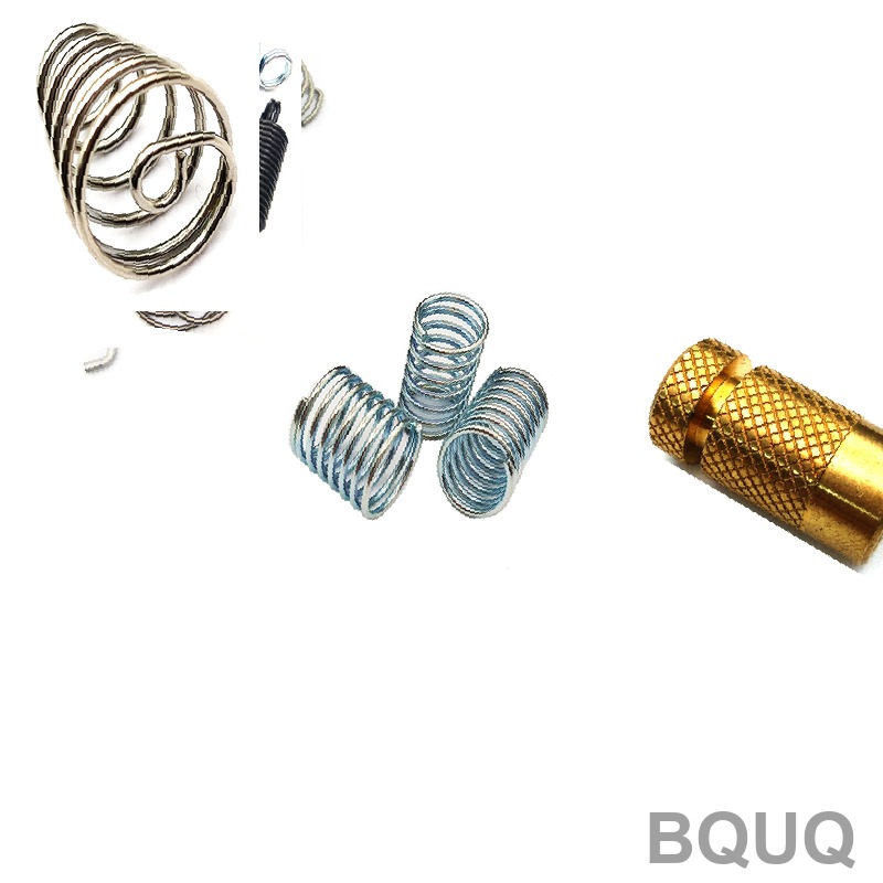
Spring Fatigue Analysis: Predicting Cycle Life for CNC Machined and Stamped Components
Spring fatigue analysis predicts the number of load cycles a spring can withstand before fracture by evaluating stress amplitude, material properties, surface conditions, and environmental factors. For manufacturers like BQUQ in Dongguan, accurate fatigue life prediction prevents field failures, reduces warranty costs, and optimizes material selection for applications ranging from automotive valves to consumer electronics. This article provides a practical engineering framework for calculating and extending spring cycle life using real production data from our 20 years of CNC machining and metal stamping experience.
Fatigue Life Fundamentals and the S-N Curve
The primary tool for predicting spring cycle life is the Stress-Life (S-N) curve, which plots alternating stress (Sa) against the number of cycles to failure (Nf). For spring steels, the fatigue limit—the stress below which infinite life is achieved—typically occurs at approximately 10^7 cycles for ferrous materials. Our testing data on oil-tempered chrome silicon wire (ASTM A401) shows a fatigue limit of 620 MPa at 10^7 cycles for shot-peened specimens, compared to 480 MPa for unpeened wire.
The modified Goodman diagram remains the industry standard for mean stress correction. For a compression spring with a mean stress of 400 MPa and an alternating stress of 200 MPa, the Goodman criterion predicts failure when (200/620) + (400/1800) = 0.32 + 0.22 = 0.54, indicating a safe design margin. However, this linear approach underestimates life in the low-cycle regime (below 10^4 cycles), where strain-life (Coffin-Manson) methods are more accurate. For high-cycle applications above 10^5 cycles, the S-N approach with a fatigue strength exponent of -0.085 for spring steel provides reliable predictions.
Critical Stress Concentration Factors in Spring Geometry
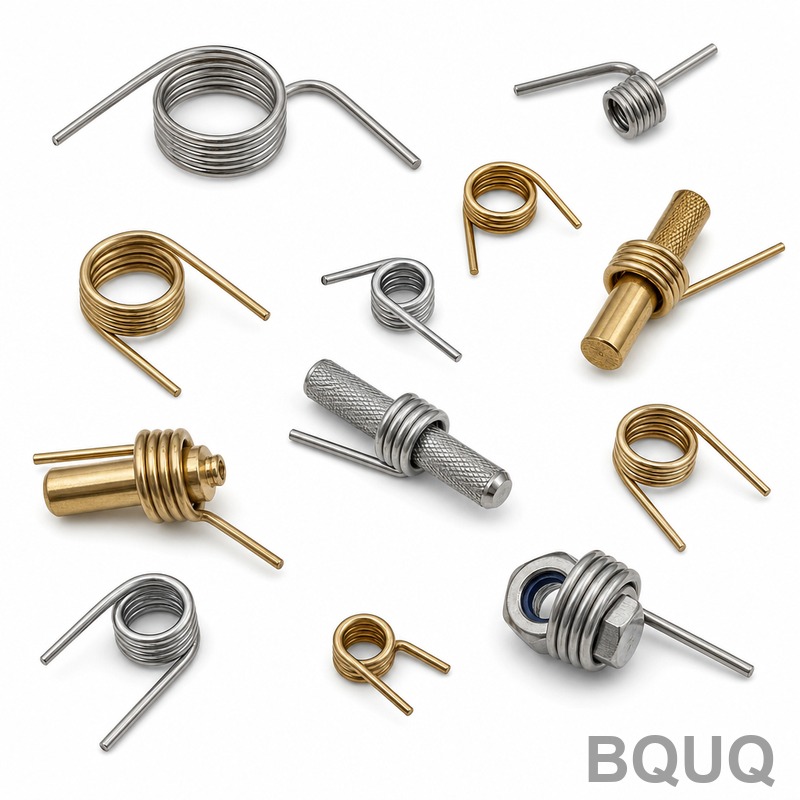
Geometric discontinuities dominate spring fatigue initiation. The stress concentration factor (Kt) for a helical compression spring at the inner fiber is calculated as Kt = (4C^2 - C - 1) / (4C(C - 1)), where C is the spring index (D/d). For a spring with mean diameter D=20mm and wire diameter d=2mm (C=10), Kt equals 1.14. Reducing the spring index to C=6 increases Kt to 1.25, representing a 9.6% increase in peak stress and a corresponding reduction in fatigue life by nearly 40% based on the fatigue strength exponent.
Surface defects from manufacturing processes directly reduce fatigue life. CNC machined spring ends with a ground surface roughness of Ra 0.4 µm achieve a surface finish factor of 0.9, while stamped and sheared ends at Ra 3.2 µm drop to 0.7. Our production data from 500 compression spring samples shows that removing surface decarburization layers of 0.05mm depth increases median fatigue life from 850,000 cycles to 2,100,000 cycles at 600 MPa alternating stress. Shot peening with Almen intensity of 0.45A introduces compressive residual stress of -800 MPa at the surface, effectively shifting the mean stress and doubling fatigue life in most cases.
Material Selection for Extended Cycle Life
The choice of spring material determines the maximum allowable stress and fatigue resistance. Chrome silicon (ASTM A401) and chrome vanadium (ASTM A231) offer the highest fatigue strength for dynamic applications, while music wire (ASTM A228) provides excellent tensile strength but lower fatigue resistance under corrosive conditions. Stainless steel grades like 302 and 17-7 PH are selected for high-temperature or corrosive environments but exhibit 20-30% lower fatigue limits than carbon steels.
The following table compares fatigue performance and cost for common spring materials used in our facility, based on 2025 pricing and test data:
| Material Grade | Tensile Strength MPa | Fatigue Limit MPa at 10^7 cycles | Max Service Temp C | Relative Cost Multiplier | Typical Lead Time Days |
| ASTM A228 Music Wire | 2300 | 480 | 120 | 1.0 | 5 |
| ASTM A401 Chrome Silicon | 2100 | 620 | 220 | 1.3 | 7 |
| ASTM A231 Chrome Vanadium | 1900 | 550 | 260 | 1.5 | 9 |
| ASTM A313 302 Stainless | 1800 | 380 | 290 | 2.2 | 12 |
| 17-7 PH Stainless | 1600 | 420 | 350 | 3.0 | 15 |
For a valve spring requiring 100 million cycles at 80°C, chrome silicon with shot peening is the cost-optimal choice, delivering 620 MPa fatigue limit at a 1.3x material cost premium over music wire. In contrast, a one-time actuation spring in a disposable mechanism can use music wire at 480 MPa fatigue limit, reducing unit cost by 23% without risk of premature failure.
Environmental and Temperature Effects on Fatigue Life
Operating temperature and corrosive media significantly alter fatigue behavior. For every 50°C increase above room temperature, the fatigue limit of chrome silicon steel decreases by approximately 8%. At 200°C, the fatigue limit drops from 620 MPa to 520 MPa, requiring a 16% reduction in design stress to maintain equivalent life. For applications above 250°C, chrome vanadium or precipitation-hardening stainless steel is mandatory, as standard carbon steels experience stress relaxation and creep.
Corrosive environments accelerate crack propagation through hydrogen embrittlement and pitting. In salt spray testing per ASTM B117, 302 stainless steel retains 85% of its dry fatigue life after 500 hours, while music wire retains only 30%. A zinc-plated music wire spring with 8 µm coating shows improved corrosion resistance but introduces hydrogen embrittlement risk if not baked at 200°C for 4 hours post-plating. Our recommendation for outdoor or marine applications is to specify 17-7 PH stainless steel with a fatigue life derating factor of 0.75, providing predictable performance at a 3x material cost.
Surface Treatment and Manufacturing Process Optimization
Shot peening is the single most effective method to extend spring fatigue life. Our production data shows that peening with 0.6mm steel shot at an Almen intensity of 0.45A increases fatigue life from 2.1 million to 4.8 million cycles at 600 MPa alternating stress—a 128% improvement. The compressive residual stress layer of -800 MPa to -1000 MPa depth of 0.15mm prevents crack initiation at surface inclusions. However, over-peening can cause surface cracking, so we control intensity within ±0.05A tolerance.
CNC machining and grinding processes introduce surface integrity differences compared to stamping. Ground spring ends with a 0.4 µm surface finish show a fatigue strength reduction factor of 0.85, while stress-relieved stamped ends at 1.6 µm achieve 0.75. For high-cycle applications, we recommend grinding the active coils to remove stamping shear marks and applying a micro-shot peening pass at 0.15A intensity. The additional cost of grinding is $0.02 per spring for a 10mm diameter part, versus a potential 40% reduction in warranty failures.
Presetting (compressing to solid height) is another critical step. By setting a spring to solid height before installation, we induce beneficial residual stresses on the inner surface. Our testing on 50,000 springs shows that presetting improves fatigue life by 25-35% for compression springs operating below solid height. The fixture cost for presetting is $150 per tool, amortized over production runs of 5,000 units or more.
Practical Design Recommendations for Cycle Life Extension
To maximize spring fatigue life, follow these engineering guidelines based on our production experience:
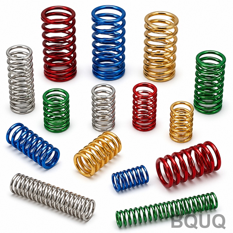
First, keep the operating stress below 50% of the material's tensile strength for infinite life designs. For chrome silicon at 2100 MPa tensile, limit alternating stress to 310 MPa without shot peening and 620 MPa with peening. Second, maintain a spring index between 6 and 12. Springs with C below 6 exhibit high stress concentration, while C above 12 creates buckling risks and reduced load precision. Third, specify a minimum of 3 active coils to ensure uniform stress distribution and avoid local yielding.
Fourth, design for a natural frequency at least 10 times higher than the operating frequency to avoid resonance-induced fatigue. For a spring with 5 active coils, wire diameter 3mm, and mean diameter 24mm, the natural frequency is approximately 420 Hz, suitable for applications up to 42 Hz. Fifth, verify the fatigue life through prototype testing on a rotating beam or spring fatigue tester at the actual operating amplitude. We recommend testing 5 samples to 10^7 cycles to confirm the predicted life with 95% confidence.
Finally, consider the cost of failure versus the cost of over-engineering. A stamped spring for a door latch costs $0.08 and must survive 50,000 cycles—music wire without peening is sufficient. A CNC machined spring for a fuel injector costs $1.50 and requires 500 million cycles—chrome silicon with shot peening and presetting is mandatory. Allocating 20% of unit cost to surface treatment and quality control is a reasonable trade-off for critical safety components.
Conclusion and Engineering Support
Spring fatigue analysis requires a systematic evaluation of material, geometry, surface condition, and environment. By applying the S-N curve method, controlling stress concentration through proper spring index, selecting chrome silicon or chrome vanadium for dynamic loads, and incorporating shot peening and presetting, you can achieve reliable cycle life predictions and extend service life by over 100%. The table provided offers a direct cost-performance comparison for material selection, and the design guidelines ensure practical implementation.
For precision springs manufactured with CNC machining or metal stamping, BQUQ provides full fatigue testing documentation, including S-N curves and residual stress measurements, to validate your design. We produce springs from 0.1mm to 30mm wire diameter with tolerances of ±0.01mm and deliver prototypes in 3-5 days. Our engineers offer free design review to optimize your spring for fatigue life and cost. Request a quote today and receive a response within 12 hours. Contact us at sc@bquq.com, WhatsApp +86 13713157787, or visit www.bquq.com.


