
Spring Rate Calculation: Formulas, Tolerances, and Practical Engineering Data
The spring rate, often denoted as 'k', is the measure of a spring's stiffness, defined as the load required to compress or extend a spring by one unit of distance, typically expressed in Newtons per millimeter (N/mm) or pounds per inch (lbf/in). To calculate it, you divide the applied force by the resulting deflection, using the formula k = F/x, but for precise manufacturing, you must use the geometric formulas for compression, extension, and torsion springs. This article provides the exact equations, real-world tolerances, and material data from a 20-year CNC and spring manufacturing facility in Dongguan to ensure your design is correct before production.
The Core Formula and Units of Measurement
The fundamental spring rate equation is linear, assuming the spring operates within its elastic limit. The formula is k = F / x, where F is the applied force in Newtons (N) and x is the deflection in millimeters (mm). The resulting rate is N/mm. In Imperial units, it is lbf/in. For engineering clarity, always specify the rate at a definitive test height, as the rate can change if the spring is compressed to solid height.
For a helical compression spring, the precise calculation is derived from the material properties and geometry: k = (G x d^4) / (8 x D^3 x Na). In this equation, G is the shear modulus of the material (e.g., 79.3 GPa for music wire), d is the wire diameter (mm), D is the mean coil diameter (mm), and Na is the number of active coils. For a spring with squared and ground ends, the total coils (Nt) minus 2 equals the active coils (Na). Ignoring the end coil effect can result in a 10-15% error in your predicted rate.
Material Selection and Shear Modulus Data
The shear modulus (G) is a critical variable in the spring rate formula. It is a material property that changes with temperature and alloy composition. Below is a table of standard materials used in our Dongguan facility, with their typical shear modulus and maximum operating temperatures. Using the wrong G value will lead to a spring that is either too soft (deflecting too much) or too stiff (overstressing the material).
| Material Grade | Shear Modulus (GPa) | Max Operating Temp (C) | Typical Wire Dia Range (mm) | Relative Cost Index |
| Stainless Steel 302 | 73.0 | 260 | 0.1 - 12.0 | 1.00 |
| Music Wire (ASTM A228) | 79.3 | 120 | 0.1 - 6.0 | 0.85 |
| Chrome Silicon (ASTM A401) | 77.5 | 230 | 1.0 - 15.0 | 1.30 |
| Oil Tempered (ASTM A229) | 79.0 | 150 | 0.5 - 12.0 | 0.90 |
| Inconel X-750 | 77.0 | 540 | 0.5 - 8.0 | 4.50 |
For precision applications, we recommend Chrome Silicon for high-stress dynamic loads above 120 degrees Celsius. For medical or corrosive environments, Stainless Steel 302 is standard, but note its lower G value, which means you need a slightly thicker wire to achieve the same rate as Music Wire.
Step-by-Step Calculation for Compression Springs
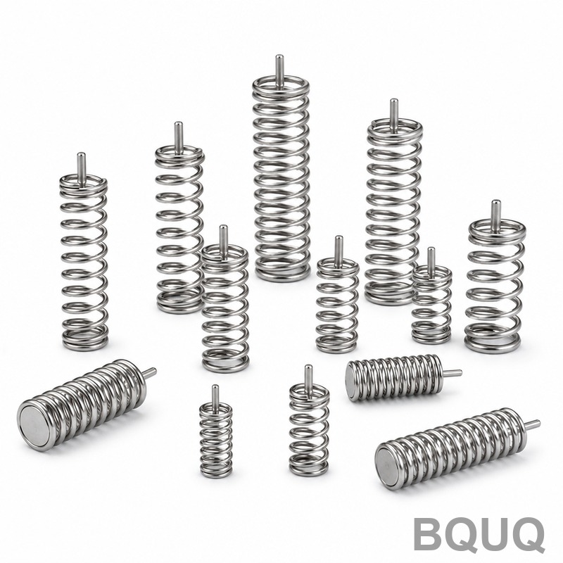
To calculate the spring rate for a custom compression spring, follow this engineering procedure. Assume you need a spring with a free length of 50 mm, an outside diameter of 20 mm, and a wire diameter of 2.0 mm. First, calculate the mean diameter (D) by subtracting the wire diameter from the outside diameter: D = 20 - 2.0 = 18.0 mm. Next, determine the number of active coils. If you require 8 total coils with squared and ground ends, Na = 8 - 2 = 6.
Using Music Wire (G = 79,300 N/mm^2), the rate calculation is: k = (79,300 x 2.0^4) / (8 x 18.0^3 x 6). This equals (79,300 x 16) / (8 x 5,832 x 6) = 1,268,800 / 279,936 = 4.53 N/mm. This means for every millimeter you compress the spring, it will resist with 4.53 Newtons of force. If your application requires a rate of 5.0 N/mm, you must adjust either the wire diameter to 2.1 mm or reduce the active coils to 5.5, as the rate is highly sensitive to wire diameter (to the fourth power).
Torsion Spring Rate and Tolerances
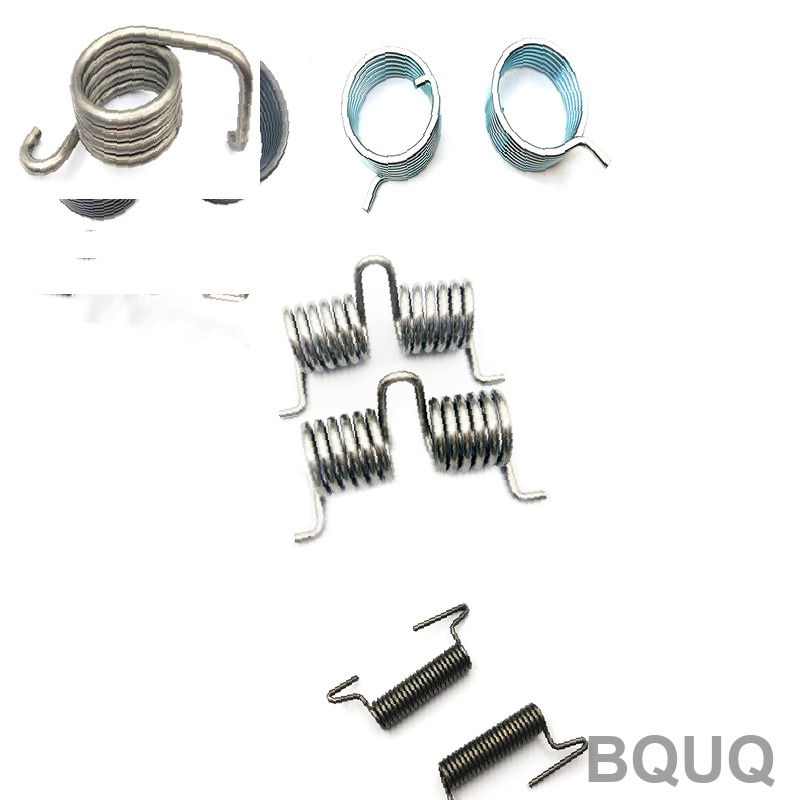
Torsion springs have a different rate calculation, measured in N-mm per degree of rotation. The formula is k = (E x d^4) / (10.8 x D x Na), where E is the Young's modulus (e.g., 196.5 GPa for Music Wire). The constant 10.8 accounts for the bending stress distribution. For a torsion spring with a 1.5 mm wire, a 12 mm mean diameter, and 4 active coils, the rate is (196,500 x 1.5^4) / (10.8 x 12 x 4) = 994,781 / 518.4 = 1,919 N-mm/degree.
Manufacturing tolerances for spring rate are typically +/- 5% for standard commercial springs, but BQUQ can hold +/- 2% on CNC coiling machines for high-volume runs. For prototype springs, the tolerance is often +/- 10% due to manual setup variations. If you require a precise rate for a safety-critical mechanism, you must specify the rate tolerance on your drawing, as a standard spring per ISO 10243 allows a variance of up to +/- 5% on the load at a specified test length.
Comparing Manufacturing Methods and Lead Times
The method of spring production directly affects the achievable tolerances and the cost per unit. CNC coiling is the standard for most custom springs, offering excellent repeatability. Hot coiling is reserved for large springs with wire diameters over 12 mm, where the material must be heated to 800-900 degrees Celsius to prevent cracking. The table below outlines the typical parameters for our production lines.
| Manufacturing Method | Wire Diameter Range | Rate Tolerance | Lead Time (Prototype) | Minimum Order Qty | Setup Cost (USD) |
| CNC Coiling (Cold) | 0.1 - 12.0 mm | +/- 2% | 3-5 days | 50 pieces | 80-150 |
| CNC Coiling (Hot) | 12.0 - 30.0 mm | +/- 5% | 7-10 days | 20 pieces | 200-400 |
| 4-Slide Forming | 0.3 - 3.0 mm | +/- 3% | 5-7 days | 500 pieces | 300-600 |
| Wire Forming (Simple) | 0.5 - 8.0 mm | +/- 5% | 1-3 days | 200 pieces | 50-100 |
For a spring rate of 4.5 N/mm with a 2.0 mm wire, a CNC coiling machine is the most cost-effective choice. If you need a complex shape with a leg bend, a 4-slide former is necessary, but the tooling cost is higher. For high-volume production (over 10,000 pieces), we recommend investing in a dedicated CNC former to reduce the per-piece cost to under $0.05.
Practical Recommendations for Design Engineers
To avoid common spring failures, verify that the spring does not reach solid height during operation. The solid height is the length when all coils touch, and the stress at solid height must not exceed 60% of the material's tensile strength. For the 4.53 N/mm spring calculated earlier, if the solid height is 16 mm (8 coils x 2.0 mm), the maximum deflection is 34 mm (50 mm free length - 16 mm solid). The load at solid height is 4.53 N/mm x 34 mm = 154 N, which must be checked against the allowable stress.
Also, consider the buckling risk for slender springs. If the free length is greater than 4 times the mean diameter, the spring may buckle sideways under compression. You should either guide the spring with a rod or bore, or reduce the free length. For our 18 mm mean diameter spring, a 50 mm free length has a slenderness ratio of 2.8, which is safe. However, if you increase the free length to 80 mm, the ratio becomes 4.4, and we recommend adding an internal guide pin.
FAQ-Style Tips on Spring Rate Accuracy
How do I measure spring rate accurately? Use a compression tester with a calibrated load cell and a linear encoder. Compress the spring to 20% of free length, record the load, then compress to 80% of the maximum deflection. The rate is the difference in load divided by the difference in deflection. Always use a preload of 1-2 N to seat the spring ends before taking measurements.
What happens if my spring rate is too high? A higher rate means the spring is stiffer, which reduces suspension travel or reduces the force applied to a mechanism. This can lead to increased stress on other components. To lower the rate, increase the number of active coils, increase the coil diameter, or reduce the wire diameter.
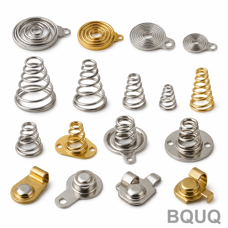
Can I calculate rate for a conical spring? Yes, but the formula is more complex. The rate is not linear because the active coils progressively come into contact. For a conical spring, the rate is calculated using an integration method, and it is typically nonlinear. We recommend using FEA simulation for these designs to predict the variable rate accurately.
Conclusion and Manufacturing Support
Calculating the spring rate is a straightforward process if you use the correct geometric formula and the accurate shear modulus for your chosen material. The critical variables are wire diameter (to the fourth power), mean coil diameter (inverse cubed), and the number of active coils. For production, always specify a rate tolerance and a test height to ensure the spring functions correctly in your assembly. A 5% error in wire diameter can result in a 21.5% error in spring rate, so precise wire sourcing is essential.
BQUQ has over 20 years of experience manufacturing springs, heat sinks, and precision CNC parts in Dongguan, China. We offer free technical review of your spring drawings and can provide a detailed rate calculation report before you commit to production. Our engineering team will verify your calculations and suggest material upgrades if your operating temperature exceeds standard limits. For a rapid response on your spring rate requirements, send us your specifications today.
Email: sc@bquq.com WhatsApp: +86 13713157787 www.bquq.com
We provide a 12-hour quotation service for all custom spring and CNC machining inquiries, ensuring your project stays on schedule.
Related Articles
- Lightweight Design and Material Upgrade of New Energy and Automobile Chassis Spring
- In-depth analysis of technology and process in the hardware spring industry in 2026: a full-dimensional interpretation of high stress, functional integration and engineering certification
- From "standard parts" to "functional parts": 2026 hardware spring industry technology trends and functional innovation engineering direction


