
What Are the Best Practices for Design for Stamping?
The direct answer is that Design for Stamping (DFS) success hinges on maintaining uniform wall thickness, utilizing generous radii, and respecting the material's minimum bend factor to avoid fractures and excessive tool wear. By adhering to these geometric constraints, you ensure part manufacturability, reduce per-unit costs, and extend die life beyond 1,000,000 strokes. Conversely, common mistakes such as sharp internal corners and tight tolerances can increase tooling costs by up to 30% and lead to catastrophic die failure.
What Are the Non-Negotiable Geometric Rules for Stamped Parts?
The physics of sheet metal forming dictates that a stamping must have consistent material flow. The first rule is to design for a constant material thickness; any coining or ironing operation to change thickness locally requires extra press tonnage and specialized tooling, increasing cost by 15-20%. The second rule involves bend radii: the inside radius must be at least 1x the material thickness (1T) for most steels, but ideally 1.5T for aluminum 5052 to prevent cracking. For hole placement, the distance from the edge of a hole to the nearest bend should be at least 2T plus the bend radius; otherwise, the hole will distort during the bending process.
How Do Tolerances Affect Tooling Cost and Production Speed?
Tolerance selection is the primary cost driver in stamping. Standard dimensional tolerances for stamped parts are typically +/- 0.005 inches (0.13 mm), while precision stamping can achieve +/- 0.001 inches (0.025 mm). However, tightening from standard to precision tolerance can increase tooling cost by 40-60% and reduce press speed from 800 SPM (strokes per minute) to 200 SPM. A common mistake is specifying tight tolerances on surfaces that are not functional. We recommend defining critical dimensions only, allowing the rest of the part to float within a standard +/- 0.010-inch envelope to optimize cycle time.
Which Material Properties Are Critical for Successful Bending?
The material's tensile strength and elongation percentage dictate formability. For low-carbon steel (CR4), the minimum bend radius is 0.5T, whereas for high-strength steel (DP980), it jumps to 4.0T. If the bend is parallel to the grain direction, the minimum radius must be increased by 50% to prevent longitudinal cracking. Additionally, the Vickers hardness of the material should be below 180 HV for intricate forming; harder materials require more tonnage and exhibit increased springback, which is typically 3-8 degrees for high-strength steels. Springback compensation requires either over-bending in the die or coining the bend area, both of which add complexity.
Why Is Hole Placement and Feature Orientation Critical?
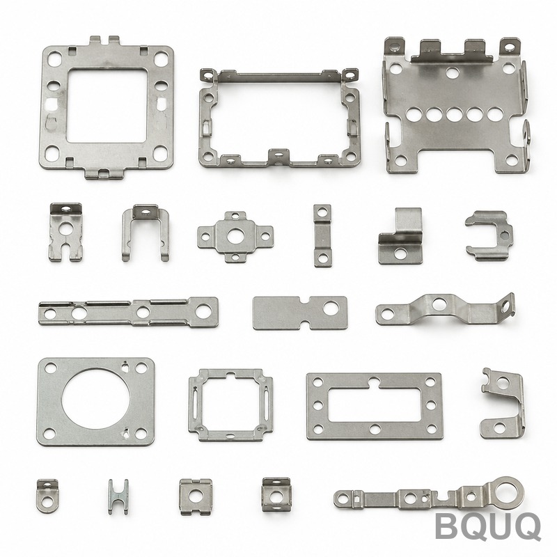
Holes are formed by punching, which creates a burnished zone and a fracture zone. For a clean cut, the hole diameter must be at least 1.2x the material thickness; punching smaller holes (e.g., 0.5 mm in 1.5 mm steel) will break the punch, leading to downtime. The distance between adjacent holes must be at least 2x the material thickness, or the webbing will distort. A frequent mistake is placing a slot too close to an edge, causing the part to "bulge" during the blanking process. The minimum distance from the edge of the part to a hole edge should be 1.5T, but 2T is safer for high-volume runs.
How Should You Design Features to Maximize Die Life?
Die life is directly tied to stress concentrations on the tool steel. Sharp internal corners (less than 0.5 mm radius) in the part profile cause stress fractures in the carbide or tool steel punches. Increasing the corner radius from 0.25 mm to 1.0 mm can triple the die life from 500,000 strokes to 1,500,000 strokes before resharpening. Additionally, the die should be designed with "shaved" or "drawn" features rather than "coined" features when possible. Coining requires 2-3 times the press tonnage and accelerates wear. For high-volume production, we recommend using progressive dies with tungsten carbide inserts for blanking stations, which maintain tolerance up to 20 million strokes, compared to 5 million for standard D2 steel.
What Is the Cost Difference Between Prototype and Production Tooling?
The cost of hard tooling for stamping is significant, but the per-part cost drops dramatically at scale. A simple two-piece die (punch and die) for a flat blank might cost $3,000, while a complex progressive die with 20 stations can cost $80,000. However, the piece price for a progressive die part might be $0.15 each, versus $2.00 for a CNC machined prototype. For low volumes (under 1,000 parts), CNC machining or 3D printing is more economical. For volumes above 10,000 parts, even a simple die set becomes cost-effective.
| Process | Tooling Cost (USD) | Lead Time (Weeks) | Unit Price (per 1000) | Tolerance (mm) | Max Material Thickness |
| CNC Prototype | $150 - $500 | 1 - 2 | $5.00 - $15.00 | +/- 0.05 | 25 mm |
| Simple Blanking Die | $3,000 - $8,000 | 3 - 4 | $0.80 - $1.50 | +/- 0.13 | 6 mm |
| Progressive Die | $15,000 - $80,000 | 8 - 12 | $0.10 - $0.30 | +/- 0.05 | 4 mm |
| Transfer Die | $25,000 - $100,000 | 10 - 14 | $0.20 - $0.50 | +/- 0.08 | 8 mm |
When Should You Use a Progressive Die Versus a Transfer Die?
The choice between progressive and transfer die technology depends on part size and complexity. Progressive dies are ideal for small to medium parts (under 150 mm square) where the strip is not separated until the final station; this ensures precision alignment but limits part complexity due to the need for a carrier strip. Transfer dies are necessary for larger parts (above 300 mm) or parts requiring deep drawing, as the part is physically moved between stations. Transfer dies cost 30-50% more than progressive dies but allow for deeper draws (depth up to 2x diameter) and more aggressive forming operations without wrinkling.
FAQ
What Is the Minimum Bend Radius for Aluminum 6061?
The minimum bend radius for 6061-T6 aluminum is 2.0x the material thickness, but this often leads to cracking. We recommend using 5052-H32 aluminum for bending applications, which allows a 1.0T radius. For any aluminum, bending across the grain is preferred to reduce fracture risk.
Can You Stamp Threads or Use Self-Clinching Fasteners?
Self-clinching fasteners are the standard method for creating threads in stamped parts. The minimum material thickness for a self-clinching nut is typically 0.04 inches (1.0 mm). You must specify a mounting hole with a tolerance of +/- 0.003 inches to ensure a proper press-in fit, and the material hardness must be below 80 on the Rockwell B scale to allow displacement.
How Do You Account for Springback in High-Strength Steel?
Springback can be compensated by adding a relief cut or a "coining" step in the die. For DP980 steel, the bend angle must be over-bent by 8-10 degrees to achieve a 90-degree final angle. Alternatively, you can specify an "air bending" process with a punch radius 10% smaller than the die radius to induce more plastic deformation.
What Is the Maximum Hole Size That Can Be Punched?
There is no strict maximum, but the hole diameter should not exceed 10x the material thickness for a single punching operation without requiring a slug lifter. For holes larger than that, we recommend a "nibbling" or "lancing" operation in the progressive die to reduce punch force. The press tonnage required to punch a hole equals the perimeter times the material thickness times the shear strength (approx. 350 MPa for steel).
When Should You Add a Relief Notch to a Bend?
A relief notch is required when a bend line intersects with an edge. This prevents the material from tearing at the corner. The relief width should be at least 1.5x the material thickness, and the depth should extend past the bend tangent line by 1T. Without this relief, the part will have a rough, torn edge that can initiate cracks in service.
How Does Part Size Affect Press Speed?
Larger parts require larger presses, which inherently run slower. A 45-ton press can run at 200 SPM for a small part, but a 400-ton press for a large automotive panel runs at 15 SPM. Additionally, the feed length of the strip material limits speed; longer feed lengths require slower accelerations to maintain material alignment.
Conclusion
Designing for stamping requires a shift in mindset from subtractive machining to forming. The key takeaway is to consult your manufacturer during the design phase, specifically regarding material grain direction and minimum radii. By integrating the rules above—specifically maintaining 1.5T radii and standard tolerances—you can reduce your tooling investment by 25% and achieve production startup in 8 weeks rather than 12. BQUQ has 20 years of experience manufacturing precision stampings, heat sinks, and springs in Dongguan, China. Our engineering team reviews every DFM (Design for Manufacturing) report within 24 hours. We offer a 12-hour quoting service for stamped parts; send your CAD files to sc@bquq.com or contact us on WhatsApp at +86 13713157787. Visit www.bquq.com to download our stamping design guide.


