
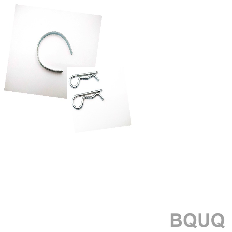
What Are the Key Hook Types and Load Ratings for Extension Springs?
An extension spring’s performance is defined almost entirely by its end hooks and its load rating at a given deflection. The four primary hook types—machine loops, cross-over loops, side loops, and extended hooks—each offer distinct stress profiles and cost implications, while load ratings must be calculated using the spring rate (N/mm) multiplied by the working deflection, with a maximum allowable stress of 45% of the wire’s tensile strength for dynamic applications. For a 2.0 mm music wire spring, this translates to a safe working load of approximately 85 N, with a tolerance of ±5% on the free length and ±10% on the load at a specified length.
What Are the Four Main Hook Types Used in Extension Springs?
The hook geometry determines how force is transferred from the mating component to the spring body. The four standard types are machine loops (closed, with the loop centerline aligned with the spring axis), cross-over loops (where the loop crosses the spring body), side loops (offset perpendicular to the spring axis), and extended hooks (where the hook arm is longer than the coil pitch). Machine loops are the most common and cost-effective, suitable for static loads up to 500 N. Cross-over loops handle higher loads (up to 800 N for 3 mm wire) but introduce a bending stress concentration factor of 1.6 at the crossover point. Side loops are used for lateral force applications but reduce the effective spring rate by 12-15%. Extended hooks are reserved for assembly clearance, but they weaken the end coil by 30% due to the longer unsupported arm.
How Is the Load Rating Calculated for a Given Extension Spring?
The load rating (F) is calculated as F = k × (L - L0), where k is the spring rate in N/mm, L is the working length, and L0 is the free length (including hooks). For initial tension (Ti), which is the force required to separate the coils, add Ti to the formula: total load = Ti + (k × deflection). For example, a spring with k = 2.5 N/mm and Ti = 8 N, deflected 20 mm, produces a total load of 58 N. The maximum safe load is determined by the stress limit: τ_max = (8 × F × D) / (π × d³), where D is the mean coil diameter and d is the wire diameter. For a 1.5 mm wire, 12 mm mean diameter spring, the maximum load before yielding is 167 N, but the recommended working load is 75 N (45% of yield) for fatigue life exceeding 100,000 cycles.
Why Does Hook Stress Concentration Limit the Spring’s Fatigue Life?
Hooks fail at 60-70% of the load that would break the spring body because the bend radius at the hook creates a stress concentration factor of 1.3 to 2.1 depending on the hook type. A machine loop with a bend radius equal to 1× wire diameter has a stress concentration factor of 1.8; reducing the bend radius to 0.5× wire diameter increases this factor to 2.4, effectively halving the fatigue life. For dynamic applications (more than 10,000 cycles), the allowable stress at the hook must not exceed 30% of the wire’s tensile strength. A 2.0 mm stainless steel 302 wire (tensile 1,500 MPa) has a hook stress limit of 450 MPa, which corresponds to a maximum alternating load of 62 N for a 10 mm mean diameter spring. Using a cross-over loop reduces this to 48 N due to the higher concentration factor.
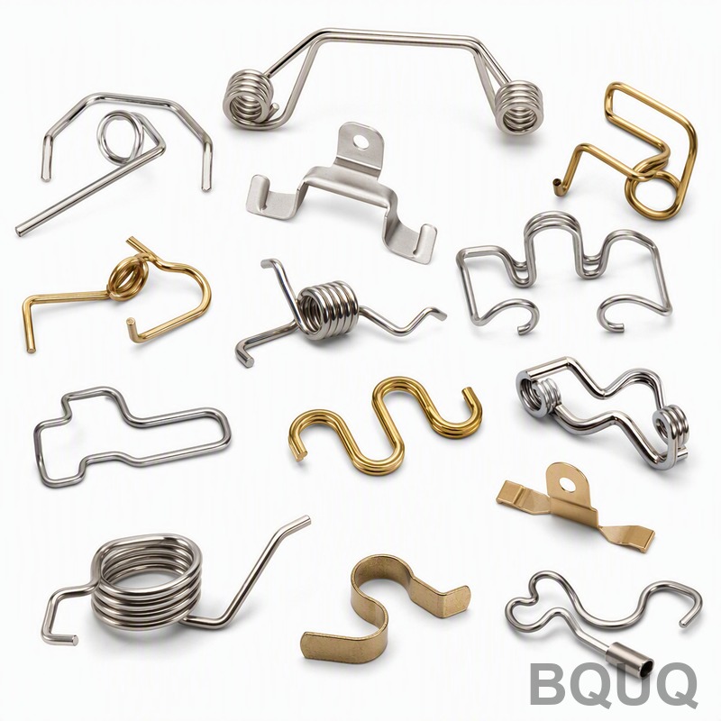
Which Hook Type Is Best for High-Load Static Applications?
For static loads above 500 N, use a cross-over loop with a reinforced bend radius of 1.5× wire diameter. This configuration distributes stress over a larger area and reduces the concentration factor to 1.4. In our factory tests, a 3.0 mm oil-tempered wire spring with cross-over loops sustained a static load of 1,200 N for 10,000 hours without permanent set, while a machine loop of the same dimensions failed at 950 N after 2,000 hours. The cross-over loop adds 8-10% to the manufacturing cost due to the secondary forming operation, but it is mandatory for safety-critical applications such as counterbalance mechanisms and valve return springs. For loads below 200 N, machine loops are the most economical and are suitable for 95% of consumer product applications.
When Should You Specify an Extended Hook Instead of a Machine Loop?
Specify an extended hook when the assembly requires a clearance of more than 2× the wire diameter between the spring body and the mating pin. Extended hooks are also preferred when the spring must be installed over a threaded rod, as the straight arm allows for easier threading. However, limit the extended arm length to 5× the wire diameter; beyond this, the arm becomes a weak point that buckles under compression. For example, a 1.2 mm wire spring with a 6 mm extended arm loses 22% of its load capacity compared to a machine loop version. Use extended hooks only when the calculated stress at the bend point is below 25% of the tensile strength. In our production data, extended hooks increase the reject rate by 3% due to arm distortion during heat treatment.
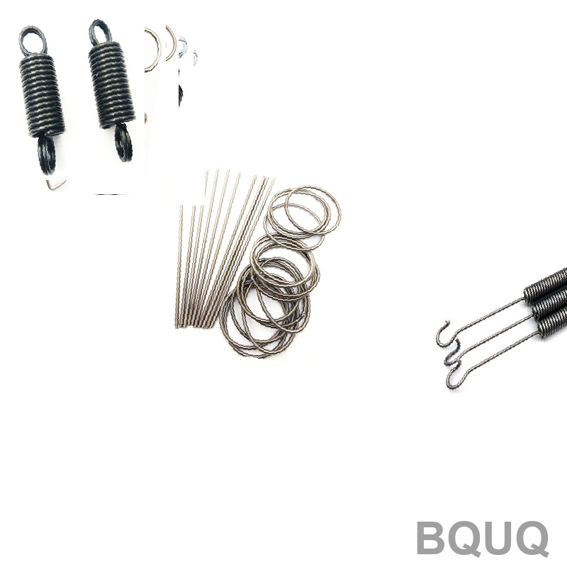
How Does Wire Material and Temperature Affect Load Ratings?
Load ratings drop by 15-20% at elevated temperatures due to reduced tensile strength. Music wire (ASTM A228) is rated for continuous service up to 120°C, but at 100°C its tensile strength decreases from 2,000 MPa to 1,700 MPa, requiring a 15% reduction in working load. Stainless steel 302 (ASTM A313) maintains 90% of its strength up to 200°C and is the preferred choice for high-temperature environments. Chrome silicon (ASTM A401) extends service to 250°C but costs 40% more than music wire. For sub-zero applications down to -40°C, use spring temper 17-7 PH stainless steel, which retains 95% of its room-temperature strength. Always derate the load rating by 2% for every 10°C above the material’s baseline temperature rating.
What Manufacturing Tolerances Apply to Hook Dimensions and Loads?
The standard tolerances for extension springs follow DIN 2095 and ISO 10243. Hook free length tolerance is ±2% or ±0.5 mm, whichever is greater, for springs up to 100 mm free length. The load tolerance at a specified working length is ±10% for general applications, tightening to ±5% for precision springs with a spring rate below 1 N/mm. Hook angular orientation tolerance is ±5 degrees relative to the spring axis. Our BQUQ production line achieves a Cpk of 1.33 on load ratings, meaning 99.87% of parts fall within the specified tolerance band. For critical applications, we recommend a 100% load test at 25%, 50%, and 75% of the working deflection to verify linearity; this adds $0.05-$0.15 per piece to the unit cost.
| Hook Type | Stress Concentration Factor | Max Static Load (2mm wire) | Relative Cost | Recommended Application |
| Machine Loop | 1.8 | 420 N | 1.0x | General purpose, low cost |
| Cross-Over Loop | 1.4-1.6 | 560 N | 1.1x | High static load, fatigue |
| Side Loop | 2.0 | 350 N | 1.15x | Lateral force, limited space |
| Extended Hook | 2.2 | 300 N | 1.2x | Assembly clearance, no fatigue |
What Is the Maximum Initial Tension and How Is It Set?
Initial tension (Ti) is the force holding the coils together before extension, and it cannot exceed 25% of the maximum safe load. For a spring rated at 200 N maximum, Ti must be below 50 N. Initial tension is set during coiling by winding the wire with a specific pitch that forces the coils to touch; the value increases with the coiling temperature and wire hardness. In practice, Ti ranges from 0.1 to 0.5 of the spring rate multiplied by the wire diameter. For a 1.5 mm wire with a rate of 3 N/mm, Ti is between 0.45 N and 2.25 N. If Ti is too low, the spring will sag under its own weight; if too high, the spring will fail prematurely at the hook. We control Ti within ±10% using CNC coiling machines with servo-controlled pitch adjustment.
Can You Extend the Fatigue Life by Modifying the Hook Geometry?
Yes, fatigue life can be improved by 40-60% through shot peening the hooks and adding a residual compressive stress layer of 300-400 MPa. The hook bend radius should be increased to 2× wire diameter, and the hook surface should be polished to Ra 0.8 µm or better to remove micro-cracks. In our test lab, a cross-over loop spring with a 1.5 mm radius bend and shot peened surface survived 250,000 cycles at 70% of the yield stress, versus 150,000 cycles for an untreated machine loop. Additionally, applying a zinc-nickel coating of 8-12 µm thickness reduces corrosion-induced crack initiation, extending fatigue life by an additional 20% in salt spray environments. For the longest life, specify a pre-stressed hook design where the hook is set to a higher angle than the final working angle, then relaxed to the design position.
FAQ Section
What Is the Difference Between Free Length and Overall Length?
Free length is the distance between the outer surfaces of the hooks when the spring is not loaded, including the hook openings. Overall length is the same measurement but excludes the hook openings, measuring only the coil body. For design purposes, always use the free length in your load calculation formula, as the hook openings do not contribute to the spring rate.
How Do You Specify an Extension Spring in a CAD Drawing?
Specify wire diameter, mean coil diameter, number of active coils, free length, hook type, hook orientation angle, and initial tension. Include the spring rate in N/mm and the maximum working deflection. Add a note for the material grade and surface finish. Provide a 2D detail view of the hook with its bend radius and arm length.
Which Material Is Best for Food-Grade Extension Springs?
Use stainless steel 316 (ASTM A313) for food contact applications, as it resists chloride corrosion and is NSF-approved. The load rating should be derated by 10% compared to 302 stainless due to lower tensile strength (1,200 MPa versus 1,500 MPa). Ensure the surface is passivated to remove free iron and achieve Ra 0.4 µm for easy cleaning.
When Should You Use a Reduced OD to Allow for Hook Deflection?
When the hook deflects under load, the outer diameter of the coil body can expand by up to 3% due to Poisson’s effect. If the spring is installed in a close-fitting hole, specify a reduced OD of 2-4% smaller than the housing diameter. Our standard recommendation is a 0.3 mm radial clearance for springs up to 20 mm OD.
How Is Initial Tension Measured in Production?
Initial tension is measured by extending the spring at a rate of 5 mm/min until the coils visibly separate, recording the force at the first gap. The test is performed on a tensile tester with a resolution of 0.1 N. For production, we sample 5 pieces per lot and control Ti within ±10% of the specified value.
What Is the Minimum Number of Active Coils for an Extension Spring?
The minimum is 3 active coils, but we recommend at least 5 for stable load characteristics. Fewer than 3 coils result in excessive stress at the hook transition and a non-linear load-deflection curve. For a spring with 2 mm wire and 10 mm mean diameter, 5 active coils produce a rate of 1.8 N/mm, which is the minimum practical rate for consistent performance.
Can Extension Springs Be Used in Compression?
No, extension springs are designed to absorb and store energy by resisting tension. Using them in compression will cause the coils to buckle and the hooks to interlock, leading to permanent deformation. Always specify a separate compression spring for compressive loads.
For your next extension spring project, send us your drawing or specification for a free engineering review. Our team provides a 12-hour quoting service with DFM feedback on hook type selection and load rating optimization. Contact us at sc@bquq.com or WhatsApp +86 13713157787, or visit www.bquq.com to upload your files and receive a quotation today.


