
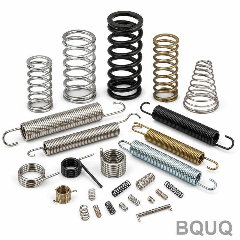
What Are the Key Technologies in CNC Spring Coiling?
CNC spring coiling technology is the precise, automated process of forming helical wire into springs using computer-controlled servo motors, tooling, and real-time dimensional feedback. The key technologies involve multi-axis servo control for consistent pitch and diameter, CNC wire feeding systems that achieve feed rates up to 120 meters per minute, and integrated laser or optical measuring systems that hold coil diameter tolerances to ±0.01 mm. This guide details the specific machine types, tooling parameters, and process controls required for manufacturing precision springs from 0.1 mm wire to 20 mm wire diameter.
What Are the Main Types of CNC Spring Coiling Machines?
The three primary machine categories are the camless 2-axis machine, the 4-axis machine, and the 8-axis or higher servo-wire forming machine. A 2-axis machine (feed and pitch) is suitable for simple compression springs with wire diameters from 0.1 mm to 3.0 mm, offering a maximum production speed of 150 parts per minute. A 4-axis machine adds independent pitch and diameter control, allowing for variable pitch springs and tighter tolerances of ±0.02 mm on outer diameter for wire up to 8.0 mm. For complex torsion springs, double-torsion springs, and wire forms, an 8-axis machine with independent servo control for each bending finger is required; these machines handle wire up to 20 mm and can produce shapes with bend angles accurate to ±0.5 degrees.
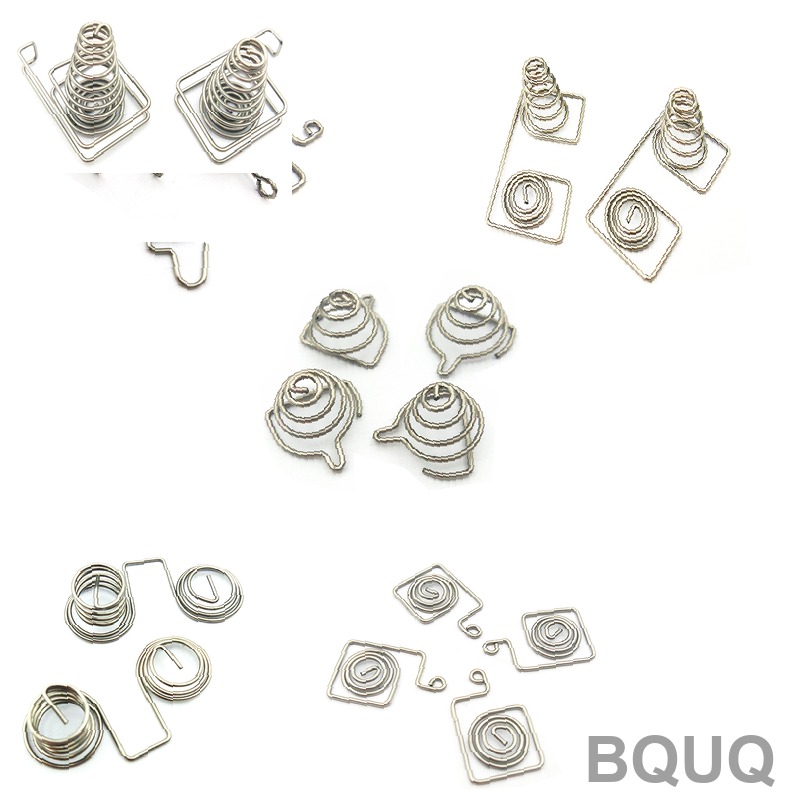
How Does the CNC Feeding System Control Wire Length and Speed?
The feeding system uses a set of powered rollers, typically two or four driven by a servo motor, that grip the wire and push it through a straightener and into the coiling point. The servo motor encoder provides a resolution of 0.001 mm, meaning the controller can stop the feed with a positional repeatability of ±0.01 mm, which is essential for holding free length tolerances on compression springs. Feed speeds vary by machine size: a small machine (0.1-1.0 mm wire) operates at 60-100 m/min, a medium machine (1.0-6.0 mm wire) at 30-60 m/min, and a large machine (6.0-20 mm wire) at 5-20 m/min. The system uses a closed-loop PID control algorithm that adjusts the servo torque in real time to compensate for wire diameter variations of up to ±0.005 mm, ensuring consistent spring pitch and index.
What Tooling Geometry Is Required for Different Spring Types?
The core tooling elements are the coiling point, the pitch tool, and the cut-off tool. For compression springs, the coiling point must have a radius that is 1.05 to 1.15 times the wire radius; a sharper point creates a smaller inner diameter but increases the risk of wire surface scoring. The pitch tool angle is typically set between 60 and 75 degrees relative to the machine axis; a higher angle is used for coarse pitch springs with a pitch-to-diameter ratio above 0.5. For torsion springs, the forming tool must be positioned with a clearance of 0.05 mm to 0.10 mm from the mandrel to allow for springback, which is typically 2 to 5 degrees for music wire and 5 to 10 degrees for stainless steel. Tool material is usually tungsten carbide (ISO K10-K20) for wire diameters under 5 mm, and high-speed steel (M42) with a hardness of 65-67 HRC for larger wire or short production runs.
How Do You Calculate Springback Compensation in CNC Programming?
Springback compensation is the angular correction applied to the coiling point and pitch tool positions to achieve the final desired geometry after the wire elastically recovers. For a given wire, the springback ratio is determined by the tensile modulus and yield strength; for example, ASTM A228 music wire has a modulus of 207 GPa and a yield strength of 1590-2070 MPa, resulting in a typical angular springback of 3 to 6 degrees per 90 degrees of bend. The CNC controller uses a compensation formula that factors in the wire diameter (d), the mandrel diameter (D), and the material factor (k): corrected angle = desired angle x (1 + k x d / D). For hard-drawn steel wire, k is 0.25; for oil-tempered chrome silicon, k is 0.30; for 302 stainless steel, k is 0.45. Most modern camless machines allow the operator to input a material constant, and the software calculates the tool paths automatically, reducing setup time by 30% compared to manual trial-and-error.
Which Materials Are Best Suited for High-Speed CNC Coiling?
Music wire (ASTM A228) is the most common due to its high tensile strength and excellent fatigue life, but it requires a coiling speed reduction of 20% to prevent overheating at the coiling point. Oil-tempered chrome silicon (ASTM A401) is preferred for high-temperature applications up to 250°C, and it can be coiled at standard speeds because its surface is less prone to galling. Stainless steel 302 (ASTM A313) offers corrosion resistance but has a higher work-hardening rate; it requires a coiling point with a larger radius (1.2 times wire radius) and a 15% slower feed rate to avoid surface cracking. For wire diameters above 10 mm, pre-heating the wire to 150-200°C reduces the required coiling force by 25% and prevents stress cracks in high-carbon alloys.
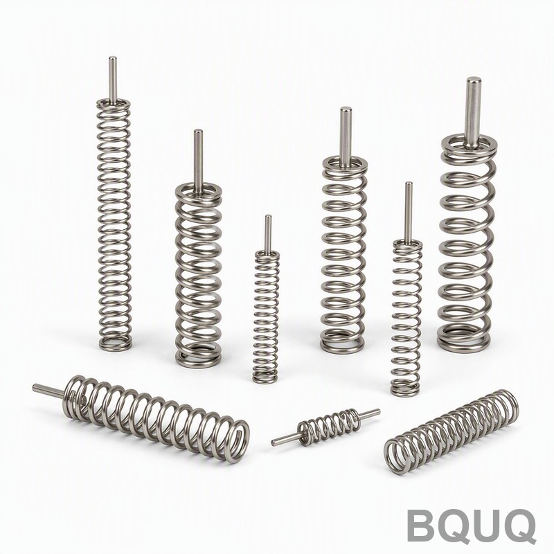
What Tolerance Classes Are Achievable with CNC Spring Machines?
The achievable tolerances depend on the machine axis count, wire diameter, and whether the spring is ground. A standard 4-axis machine can hold an outer diameter tolerance of ±0.05 mm for wire up to 3 mm, and ±0.10 mm for wire up to 10 mm, which corresponds to DIN 2095 Grade 2. For precision applications, using an 8-axis machine with a laser measurement system allows for dynamic in-process correction, achieving DIN 2095 Grade 1 tolerances: free length ±0.02 mm, outer diameter ±0.03 mm, and total number of active coils ±0.25 coils. The following table summarizes typical achievable tolerances and production parameters:
| Parameter | 2-Axis Machine | 4-Axis Machine | 8-Axis Machine |
| Wire diameter range | 0.1 - 3.0 mm | 0.5 - 8.0 mm | 1.0 - 20.0 mm |
| Max feed speed | 100 m/min | 60 m/min | 20 m/min |
| Outer diameter tolerance | ±0.08 mm | ±0.05 mm | ±0.03 mm |
| Free length tolerance | ±0.15 mm | ±0.05 mm | ±0.02 mm |
| Angular accuracy (torsion) | N/A | ±1.0 degree | ±0.5 degree |
| Typical setup time | 15 min | 30 min | 60 min |
| Machine base price range | USD 25,000 - 45,000 | USD 60,000 - 120,000 | USD 180,000 - 350,000 |
How Does In-Process Measurement Improve Spring Quality?
In-process measurement uses a laser micrometer or a CCD camera system mounted immediately after the coiling point to measure the outer diameter and pitch of every spring at a rate of 200 measurements per second. The measurement data is fed back to the CNC controller, which adjusts the coiling point position in increments of 0.001 mm to correct for thermal drift and wire hardness variation. This closed-loop system reduces the rejection rate from a typical 3% to below 0.5% for high-volume production runs. For critical applications such as automotive valve springs, a 100% inspection system also includes a load tester that checks the spring rate at two deflection points, with a load tolerance of ±2% of the specified value.
Can CNC Coiling Replace Traditional Grinding for End Coils?
CNC coiling cannot replace grinding for closed and ground ends; the coiling process only forms the wire, it does not flatten the end surfaces. A CNC machine can produce a closed end coil (no gap between the first and second coil) by programming the pitch tool to zero pitch for the final 0.75 turns, but the end surface will be cut by the wire cut-off tool at an angle. For springs requiring a flat seating surface, a secondary grinding operation is mandatory; the typical grinding allowance is 0.10 mm to 0.25 mm per end, and the resulting flatness is ±0.03 mm. However, CNC coiling can reduce the grinding stock by 50% compared to manual coiling because the wire feed length is controlled to ±0.01 mm, which minimizes the variation in the unground free length.
What Maintenance Schedule Is Required for CNC Spring Machines?
Critical maintenance includes daily cleaning of the coiling point and pitch tool with a solvent to remove wire drawing compounds, and weekly inspection of the feed rollers for wear, which should be replaced when the roller groove depth exceeds 0.02 mm. The gearbox and cam shafts require lubrication every 500 operating hours with ISO VG 220 gear oil, and the servo motor encoders should be checked for alignment every 2000 hours. The wire guide tubes should be inspected for scoring every week; a scored guide will cause wire surface defects and inconsistent coiling force. For high-speed operation above 80 m/min, the coiling point temperature can reach 180°C, so a water-cooled tool holder is recommended to extend tool life from 8 hours to 40 hours between re-sharpening.
FAQ
What Is the Minimum Wire Diameter That Can Be CNC Coiled?
The minimum wire diameter for a production CNC spring machine is 0.1 mm, achievable on a 2-axis machine with a high-precision servo feed. Below 0.1 mm, wire handling and feeding become unreliable, and tolerance control (outer diameter ±0.08 mm) becomes difficult to maintain. For wire under 0.3 mm, a machine with a wire straightener using 5 or more rollers is required to prevent coil set.
How Long Does a CNC Spring Machine Setup Take?
A basic compression spring setup on a 2-axis machine takes 15 minutes, while a complex torsion spring on an 8-axis machine requires up to 60 minutes for tool mounting and program verification. Using the machine's automatic tool positioning and stored program memory reduces repeat setup time to under 10 minutes for previously run parts. The setup time is directly proportional to the number of axes; each additional tool axis adds about 5 minutes of alignment time.
What Is the Cost Difference Between CNC Coiling and Traditional Cam Coiling?
A CNC camless machine costs USD 25,000 to 350,000 depending on axis count, while a traditional cam-operated machine costs USD 15,000 to 80,000. However, the CNC machine reduces changeover time by 70% and allows in-process tolerance correction, lowering the per-part cost for runs under 50,000 pieces by 15-20%. For runs above 100,000 pieces, a cam machine may be cheaper per part if no dimensional changes are required.
Which Spring Materials Cannot Be CNC Coiled?
Materials with very low ductility, such as fully hardened tool steel (above 60 HRC) or cast iron, cannot be coiled because they will crack at the required bend radius. Titanium alloys can be coiled but require a 50% slower feed speed and a heated coiling point at 300°C to prevent springback variations. Beryllium copper is coilable but requires a specialized lubricant to prevent surface galling.
How Do You Prevent Wire Surface Damage During Coiling?
Wire surface damage is prevented by using a coiling point with a radius 1.1 times the wire radius, ensuring the wire enters the coiling point at a straight angle, and applying a consistent film of water-soluble lubricant at a rate of 0.5 liters per hour. The feed rollers must have a groove radius exactly matching the wire radius; a mismatch of 0.02 mm causes pressure marks. For stainless steel, a molybdenum disulfide coating on the coiling point reduces friction and prevents pick-up.
Can a CNC Spring Machine Produce Non-Circular Spring Shapes?
Yes, an 8-axis CNC machine can produce conical, barrel, and hourglass springs by independently controlling the diameter tool position along the wire feed length. The diameter can be changed every 0.5 mm of wire feed, allowing for smooth conical profiles with a taper angle accuracy of ±0.2 degrees. For rectangular wire or shaped wire, a specialized wire straightener and a custom coiling point are required.
What Is the Typical Lead Time for Custom Spring Production?
For a standard compression spring with a wire diameter under 3 mm, BQUQ can provide samples in 3-5 working days and production quantities in 7-10 working days. For complex torsion springs or wire forms requiring 8-axis coiling and custom tooling, the lead time is 10-15 working days. Tooling design is included in the sample cost, and production tooling is amortized over the first order.
CNC spring coiling technology is a high-precision manufacturing process that demands a thorough understanding of machine axis architecture, tool geometry, material properties, and in-process measurement to achieve consistent results. The choice between a 2-axis, 4-axis, or 8-axis machine must be based on the required tolerance class, wire diameter, and production volume, as outlined above. For engineering teams seeking a reliable manufacturing partner with 20 years of experience in precision springs and wire forms, BQUQ offers a 12-hour quoting service for your drawings. Contact us at sc@bquq.com or WhatsApp +86 13713157787, or visit www.bquq.com to discuss your project requirements.
Related Articles
- Smart Spring Inventory Management Strategies for OEMs
- Lightweight Design and Material Upgrade of New Energy and Automobile Chassis Spring
- In-depth analysis of technology and process in the hardware spring industry in 2026: a full-dimensional interpretation of high stress, functional integration and engineering certification


