
What Is a Heat Sink Baseplate and Why Does Flatness Matter?
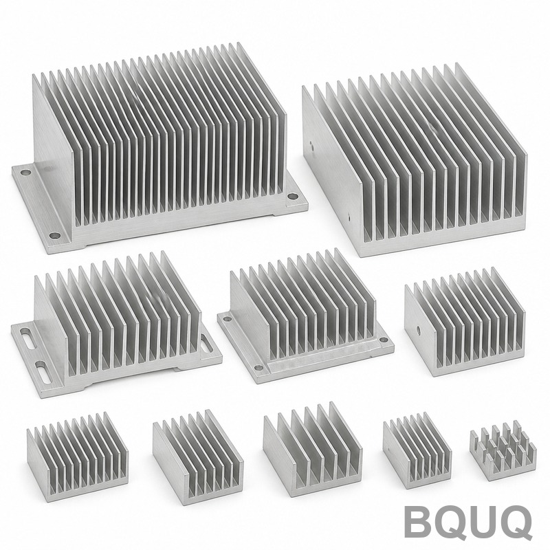
A heat sink baseplate is the solid metal foundation of a heat sink assembly that directly contacts the heat source, typically a CPU, IGBT, or power module, to spread thermal energy into attached fins or heat pipes. Flatness matters because it determines the size of the air gap between the baseplate and the component surface, which directly controls thermal resistance; a 0.05 mm deviation can increase thermal resistance by over 20% and cause junction temperatures to rise by 10-15°C. In practical terms, achieving a flatness of 0.05 mm or better across a 100 mm square baseplate is the difference between a reliable 80°C operating temperature and a premature failure at 105°C.
How Does Baseplate Flatness Affect Thermal Performance?
The fundamental principle is that air is a thermal insulator with a conductivity of only 0.026 W/m·K, while aluminum conducts at 150-200 W/m·K and copper at 380-400 W/m·K. When a baseplate is not flat, the contact area between the baseplate and the heat source is reduced, and the voids fill with air or thermal interface material (TIM). For a typical 50 mm x 50 mm IGBT module, a flatness deviation of 0.10 mm reduces the effective contact area by 35-40%, forcing the TIM layer to bridge the gap. Since most TIMs have a thermal conductivity of 1-8 W/m·K, the thermal resistance of the interface can increase from 0.05 °C/W to 0.12 °C/W, which translates to a 15-20°C higher case temperature at 300 W of dissipated power. The industry rule of thumb is that every 0.025 mm of flatness deviation adds approximately 0.02 °C/W of thermal resistance for a 100 cm² interface.
What Flatness Tolerance Should a Heat Sink Baseplate Have?
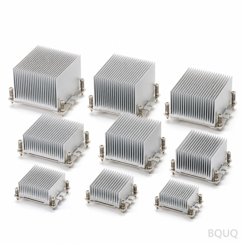
The required flatness tolerance depends on the baseplate size, mounting method, and the thermal budget of the application. For standard aluminum baseplates up to 150 mm in length, a flatness of 0.05 mm total indicated reading (TIR) is typical for consumer electronics, while high-performance server and telecom applications demand 0.03 mm TIR. For larger baseplates exceeding 300 mm, such as those used in railway traction converters, the tolerance relaxes to 0.10 mm TIR due to material stress and warpage during machining. Copper baseplates, which are softer and more prone to warpage, typically require a post-machining stress relief step to maintain 0.05 mm TIR. In our CNC machining facility, we routinely hold 0.02 mm flatness on 200 mm x 200 mm aluminum baseplates using vacuum chucks and multi-step milling, but this adds 15-20% to the machining cost compared to a 0.10 mm tolerance.
Which Materials Are Best for Heat Sink Baseplates?
The two dominant materials are aluminum 6063-T5 and copper C1100, with aluminum being the default choice for 85% of applications due to cost and weight. Aluminum 6063-T5 offers a thermal conductivity of 200 W/m·K, a density of 2.7 g/cm³, and a material cost of approximately $4-6 per kilogram, making it ideal for natural convection and forced air cooling. Copper C1100 provides 390 W/m·K conductivity but costs $12-15 per kilogram and weighs 8.9 g/cm³, which is why it is reserved for high-density power electronics where space is constrained and heat flux exceeds 50 W/cm². A hybrid option, copper baseplate with aluminum fins, is used in high-end IGBT modules, but the bimetallic interface requires careful design to manage differential thermal expansion, which can cause flatness changes of 0.02-0.04 mm over a 100°C temperature swing. For extreme applications, molybdenum-copper (MoCu) and copper-tungsten (CuW) composites offer thermal expansion matching with ceramics but cost $80-200 per kilogram.
Why Does Machining Stress Cause Baseplate Warpage?
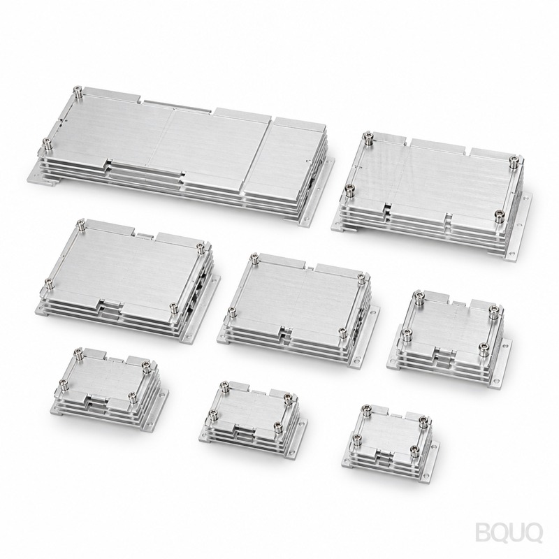
When a heat sink baseplate is machined from a solid block or plate, the removal of material releases internal stresses that were locked in during the rolling or extrusion process. For example, a 10 mm thick aluminum plate that is machined down to 6 mm on one side will bow by 0.10-0.30 mm because the remaining material is thinner on one side and the internal stress distribution becomes unbalanced. The cutting process itself also introduces residual stress: a typical face milling operation with a 0.5 mm depth of cut generates surface compressive stresses of 50-150 MPa, which can cause the baseplate to curl upward at the edges. To minimize this, manufacturers use a two-step machining process: rough machining to within 0.3 mm of final thickness, followed by a stress-relief heat treatment at 180-220°C for 2-4 hours, then a finish machining pass. This process reduces warpage by 60-70%, but it adds 8-12 hours to the production lead time and 10-15% to the cost. An alternative is to use pre-stress-relieved plate material, which costs 5-8% more but eliminates the need for post-machining heat treatment.
How Should a Baseplate Be Mounted to Maintain Flatness?
The mounting method has as much influence on final flatness as the machining process, because clamping forces can deform a baseplate that was perfectly flat when unconstrained. The recommended approach is to use a distributed screw pattern with a pitch of 20-30 mm around the perimeter and a torque of 0.5-1.0 N·m for M3 screws, rather than a few high-torque screws in the corners. For baseplates larger than 100 mm, a center-mounted spring clip or a compression plate is advised to distribute the load evenly. The mounting surface on the chassis or cold plate must also be flat, ideally within 0.05 mm, because a baseplate will conform to its mounting surface under pressure; if the mounting surface has a 0.15 mm bump, the baseplate will deform locally, creating a void directly under the heat source. Thermal interface materials should be applied at a controlled thickness of 0.05-0.10 mm for phase-change materials and 0.10-0.20 mm for silicone-based greases, using a stencil or dispensing robot to ensure uniformity. In our testing, a properly mounted flat baseplate with 0.03 mm flatness achieves a thermal resistance of 0.04 °C/W, while the same baseplate mounted on a warped surface with 0.15 mm deviation degrades to 0.09 °C/W.
Which Surface Finish Is Required on a Heat Sink Baseplate?
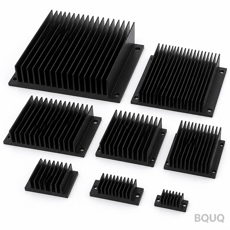
The surface finish of the baseplate contact area is specified as Ra (arithmetic average roughness) and should be between 0.4 and 1.6 µm for most applications, with 0.8 µm being the industry standard for TIM-based interfaces. A surface that is too rough, above 3.2 µm, creates microscopic peaks that prevent the TIM from filling the valleys, leaving air pockets that increase thermal resistance. A surface that is too smooth, below 0.2 µm, can cause the TIM to be squeezed out completely under pressure, resulting in metal-to-metal contact that is actually worse because it has a higher contact resistance due to microscopic gaps. The flatness and surface finish are independent specifications: a baseplate can be perfectly flat but have a rough finish, or smooth but warped, and both conditions are unacceptable. For direct metal-to-metal contact without TIM, which is rare and requires liquid metal or indium foil, the flatness must be improved to 0.01 mm and the finish to 0.2 µm, but this is only feasible for small baseplates under 50 mm. Standard CNC machining with a fine finish pass at 0.1 mm depth of cut and a feed rate of 0.05 mm/revolution reliably produces 0.8 µm Ra on aluminum.
What Are the Typical Costs and Lead Times for Machined Baseplates?
The cost of a heat sink baseplate is driven by material, machining time, and tolerance requirements, with flatness being the largest cost driver. For a 100 mm x 100 mm x 8 mm aluminum baseplate with a flatness of 0.10 mm, the machining cost is $8-12 per piece for quantities of 500-1000 units, with a lead time of 2-3 weeks including material procurement. Tightening the flatness to 0.03 mm increases the cost to $15-20 per piece due to additional setup, slower feed rates, and a higher scrap rate of 3-5% versus 1% for standard tolerance. For copper baseplates of the same size, the material cost is $15-18 per piece and machining adds $20-25 due to the higher cutting forces and tool wear; copper machining produces 2-3 times more tool wear than aluminum. The table below summarizes typical pricing and specifications for common baseplate configurations.
| Specification | Aluminum 6063-T5 | Copper C1100 | MoCu Composite |
| Thermal Conductivity (W/m·K) | 200 | 390 | 180-200 |
| Density (g/cm³) | 2.7 | 8.9 | 10.0 |
| Typical Flatness (mm TIR) | 0.05 | 0.05 | 0.03 |
| Surface Finish (Ra, µm) | 0.8 | 0.8 | 0.4 |
| Material Cost per kg (USD) | 4-6 | 12-15 | 80-200 |
| Machining Cost per 100x100mm part (USD) | 8-20 | 20-45 | 60-120 |
| Lead Time (weeks) | 2-3 | 3-4 | 4-6 |
| Max Operating Temperature (°C) | 150 | 200 | 300 |
When Should You Use a Copper Baseplate Instead of Aluminum?
The decision between copper and aluminum baseplates is based on the heat flux and the available space for the heat sink. If the heat source generates more than 30 W/cm² of heat flux and the heat sink dimensions are constrained by the enclosure, copper is necessary because its 390 W/m·K conductivity spreads heat laterally at nearly twice the rate of aluminum, reducing the temperature gradient across the baseplate. For example, a 200 W IGBT module with a 40 mm x 40 mm die area produces 125 W/cm², which requires a copper baseplate to keep the junction temperature below 125°C; an aluminum baseplate would be 15-25°C hotter under the same conditions. However, if the heat sink has ample fin surface area and airflow, an aluminum baseplate with a vapor chamber or heat pipes embedded can achieve similar performance at 40-50% lower cost. Copper baseplates also have a higher coefficient of thermal expansion (17 ppm/°C versus 23 ppm/°C for aluminum), which is better matched to ceramic substrates (6-8 ppm/°C), reducing solder joint stress in power modules. For production volumes above 10,000 units per year, the material cost difference of $8-10 per part becomes significant, so a detailed thermal simulation should be performed to justify copper.
FAQs
What is the difference between flatness and surface roughness?
Flatness is a measure of the overall waviness or deviation of the entire surface from a perfect plane, typically expressed in millimeters of total indicator reading, while surface roughness (Ra) measures the fine microscopic peaks and valleys on the surface. A surface can be very rough but perfectly flat, or very smooth but warped, and both parameters must be controlled independently for proper thermal contact.
How is baseplate flatness measured in production?
Flatness is measured using a granite surface plate with a dial indicator or a coordinate measuring machine (CMM) that scans the surface at multiple points, typically 9 to 25 measurement points for a 100 mm square baseplate. The flatness value is the difference between the highest and lowest points relative to the reference plane, and measurements should be taken at a controlled temperature of 20°C because aluminum expands by 0.023 mm per meter per degree Celsius.
Can a warped baseplate be straightened after machining?
Yes, a warped baseplate can be straightened using a press or roller leveler, but this is only reliable for aluminum and only if the warpage is less than 0.2 mm. Straightening introduces new residual stresses that can cause the baseplate to warp again during thermal cycling, so it is better to prevent warpage through proper machining and stress relief rather than attempting to correct it afterward.
What is the maximum size for a heat sink baseplate?
Heat sink baseplates can be manufactured up to 600 mm x 600 mm in a single piece using large CNC machining centers, but flatness control becomes increasingly difficult above 300 mm due to material stress and the need for specialized vacuum fixturing. For larger sizes, it is common to use multiple smaller baseplates or to specify a looser flatness tolerance of 0.15-0.20 mm, which may require a compliant TIM layer or a spring-loaded mounting system.
How does the baseplate thickness affect thermal performance?
A thicker baseplate spreads heat more effectively in the lateral direction but adds thermal resistance in the vertical direction, so there is an optimal thickness for each application. For aluminum, the optimal baseplate thickness is typically 6-10 mm for heat sources up to 50 W/cm², while copper can be thinner at 3-6 mm due to its higher conductivity; going beyond 12 mm for aluminum provides diminishing returns because the added material increases weight and cost without significant temperature reduction.
Does the baseplate need a protective coating?
Bare aluminum and copper baseplates will oxidize over time, which can increase surface roughness and degrade thermal contact, so a protective coating is recommended for harsh environments. The most common options are a clear anodize coating (5-10 µm thick) for aluminum, which adds 2-5°C of thermal resistance, or a nickel plating (5-15 µm) for copper, which maintains a stable surface and improves solderability for power module attachment.
At BQUQ, we have manufactured precision heat sink baseplates for over 20 years, specializing in CNC machining with tight flatness control down to 0.02 mm and surface finishes of 0.4 µm Ra. Our engineering team can review your thermal requirements and recommend the optimal baseplate material, flatness tolerance, and surface finish for your application. We provide free DFM feedback within 12 hours of receiving your drawings, and our quoting team will respond with detailed pricing and lead times within 12 hours. Contact us at sc@bquq.com or via WhatsApp at +86 13713157787, or visit www.bquq.com to upload your files and receive a quote today.
Related Articles
- Heat Sinks for Battery Packs: Prevent Thermal Runaway
- Thermal Management for High Brightness LEDs with Heat Sinks
- New energy vehicle IGBT heat dissipation, heat sink reliability engineering, heat pipe and temperature plate integrated heat sink, surface treatment and heat radiation enhancement: anodic oxidation, black coating and micro-nano structure, graphene/3D printing/intelligent thermal management: 2030 heat sink technology roadmap


