
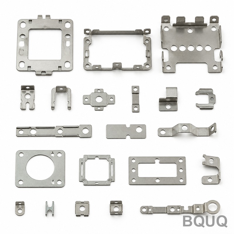
What Is Burr in Metal Stamping and How Do You Control It?
A burr in metal stamping is an undesirable raised edge or small piece of material that remains attached to a workpiece after the cutting or shearing process. Burrs form when the punch and die clearance is incorrect, tooling is worn, or material ductility exceeds the fracture point, leaving a deformed lip at the cut edge. You control burrs by optimizing die clearance (typically 5-10% of material thickness per side), maintaining sharp tooling, and applying secondary deburring processes such as vibratory finishing or electrochemical deburring when tolerances demand it.
What Exactly Causes Burr Formation During the Stamping Process?
Burr formation is a mechanical result of the four-phase shearing sequence: elastic deformation, plastic deformation, fracture initiation, and separation. When the punch penetrates the sheet metal, it compresses the material; if the clearance between punch and die is too large, the fracture lines from the punch and die do not meet, causing the material to stretch and tear instead of shearing cleanly. This tearing leaves a jagged, raised protrusion on the part edge, typically measuring between 0.05 mm and 0.3 mm in height depending on material thickness and tensile strength. For example, stamping 2.0 mm thick stainless steel (SUS304) with a clearance of 0.3 mm per side will produce burrs of approximately 0.15 mm, while a properly tuned clearance of 0.12 mm per side reduces that to under 0.05 mm.
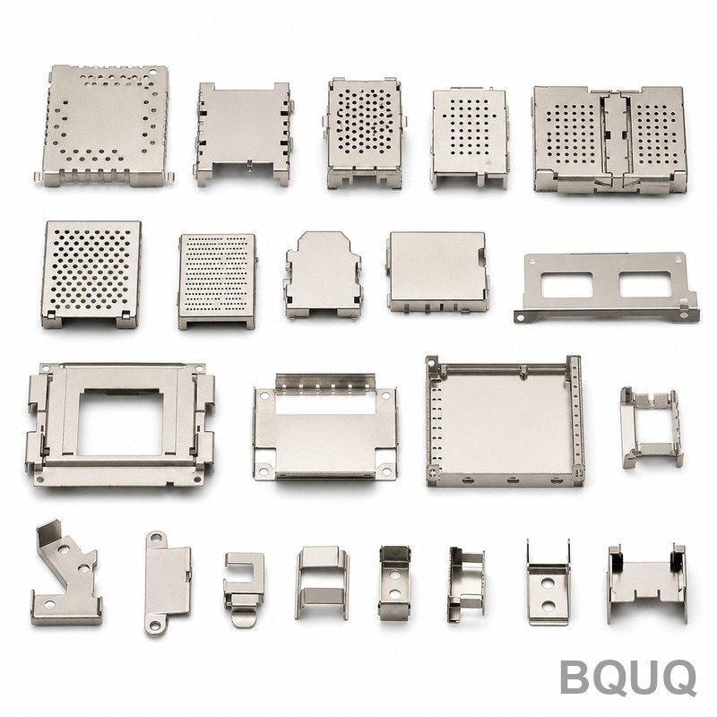
How Does Die Clearance Affect Burr Size and Edge Quality?
Die clearance is the single most influential parameter in burr control. The optimal clearance is typically 5% to 10% of the material thickness per side for most carbon steels, but this varies with material type: aluminum requires 4-6%, stainless steel requires 8-12%, and copper alloys require 6-8%. If clearance is too small, the punch and die edges fracture prematurely, creating a secondary shear zone and a large, sharp burr on the punch side. If clearance is too large, the material bends excessively before fracture, producing a rollover and a heavy burr on the die side. At BQUQ, we set clearance using the formula C = 0.006 + (0.006 x material thickness) for mild steel, which yields burr heights below 0.08 mm on parts up to 3.0 mm thick.
How Can Tooling Wear Be Detected and Prevented to Minimize Burrs?
Tooling wear is the primary culprit for burr growth over a production run. A sharp punch edge has a radius of less than 0.02 mm; as the tooling experiences wear, this radius increases to 0.05 mm or more, causing the material to flow around the edge rather than shear, which directly increases burr height. You can detect wear by monitoring burr height trends: if burr height increases by 50% above the baseline within 10,000 strokes, inspect the punch and die edges for chipping or rounding. Preventive measures include using high-chromium tool steel (SKD11) or powder metallurgy steel (such as ASP23) with a hardness of 60-62 HRC, and applying TiCN or TiAlN coating to extend tool life by 2-3 times. At 200 strokes per minute, a typical progressive die should be re-sharpened every 500,000 to 800,000 strokes; failure to do so will increase burr height from 0.05 mm to over 0.2 mm.
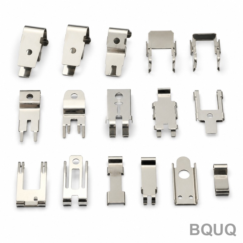
Why Do Different Materials Produce Different Burr Characteristics?
Material properties dictate how the sheet metal fractures under shear stress, directly influencing burr size and shape. High-ductility materials like aluminum 5052 and copper C1100 tend to produce larger, more irregular burrs because they undergo significant plastic deformation before fracture, requiring tighter clearances and higher punch speeds. Conversely, high-strength materials like stainless steel 301 full-hard or spring steel C75 produce smaller but harder burrs that are more difficult to remove, often necessitating grinding or abrasive flow deburring. For example, stamping 1.5 mm thick aluminum 6061-T6 with standard clearance yields a burr of 0.25 mm, but reducing clearance to 4% lowers it to 0.10 mm. Material hardness also matters: a material with a hardness of 80 HRB will produce a smooth shear zone, while a hardness above 95 HRB creates a more brittle fracture and a smaller but sharper burr.
Which Deburring Methods Are Most Effective for Different Stamping Applications?
The choice of deburring method depends on part geometry, production volume, and required edge tolerance. Vibratory finishing is the most cost-effective for small to medium parts, with a cost of $0.005 to $0.02 per part, and it removes burrs up to 0.1 mm using ceramic or plastic media over a cycle time of 15 to 45 minutes. For high-precision parts, electrochemical deburring (ECD) is preferred because it selectively removes burrs without affecting the main surface, achieving edge radii of 0.1 to 0.3 mm with a cycle time under 30 seconds, though tooling costs start at $1,500 per fixture. Manual deburring with a rotary tool remains viable for prototypes or low volumes at $2 to $5 per part, but it is inconsistent and unsuitable for production. For large flat parts, a brushing machine with abrasive nylon brushes is recommended, running at 1,400 RPM and removing burrs of 0.2 mm at a line speed of 3 meters per minute.
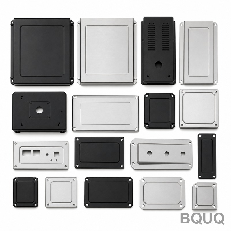
How Can Burr Control Be Integrated Into the Die Design Phase?
Burr control must begin at the design stage, not after production has started. During die design, you should specify the punch-to-die clearance based on material thickness and type, include a cutting edge angle of 0.5 to 1.0 degrees on the punch to reduce friction, and design for slug shedding to prevent tooling damage. Additionally, adding a small shear angle (0.5 to 2 degrees) on the punch face reduces impact force and burr formation, but it increases the required press tonnage by 10-15%. You should also design the part with the burr side facing a non-critical surface, since burrs always form on the side opposite the die. At BQUQ, we use CAD simulation software to predict burr location and height, which allows us to adjust the die geometry before tooling steel is cut, saving an average of 15% in tooling costs and reducing trial-and-error iterations by 40%.
What Are the Industry Standards for Acceptable Burr Height?
Industry standards define acceptable burr height based on part function and material thickness. The most common reference is DIN 267 Part 11, which specifies maximum burr heights of 0.1 mm for parts under 2.0 mm thickness and 0.15 mm for parts from 2.0 to 6.0 mm thickness. For automotive applications, many OEMs follow the VDA 19 standard, which requires burrs below 0.05 mm for sealing surfaces and below 0.1 mm for structural parts. In electronics and precision components, the acceptable burr is often 0.03 mm or less, requiring secondary processes like micro-deburring or laser deburring. The table below summarizes typical burr limits by industry:
| Industry | Material Thickness Range | Maximum Burr Height | Typical Deburring Method |
| Automotive structural | 1.0 - 3.0 mm | 0.10 mm | Vibratory finishing |
| Electronic connectors | 0.2 - 1.0 mm | 0.03 mm | Electrochemical deburring |
| Aerospace components | 1.5 - 4.0 mm | 0.05 mm | Manual or abrasive flow |
| Medical devices | 0.5 - 2.0 mm | 0.02 mm | Micro-blasting or ECD |
| General industrial | 0.5 - 6.0 mm | 0.15 mm | Brush deburring |
When Should Secondary Burr Removal Be Avoided for Cost Efficiency?
Secondary burr removal should be avoided when the burr is functionally acceptable and the cost of removal exceeds the benefit. For non-critical parts like mounting brackets, washers, or internal components that do not contact sealing surfaces or moving parts, a burr height up to 0.15 mm is often acceptable, and adding a deburring step would increase part cost by 10-30% without adding value. You should also avoid secondary processes for high-volume parts where the tooling can be optimized to produce burrs below 0.05 mm consistently, because vibratory finishing at 10,000 parts per hour costs approximately $0.01 per part, which adds up to $100 per hour of production. Instead, invest in higher-quality die steel and more frequent maintenance, which can reduce the need for deburring by 70% and lower total cost per part by 15%.
How Do You Measure Burr Height Accurately in a Production Environment?
Accurate burr measurement requires the right equipment and sampling frequency. The simplest method is a dial indicator with a flat anvil, which measures burr height to a resolution of 0.01 mm, but it is operator-dependent and slow. For production monitoring, use an optical comparator or a digital microscope with a 20x to 50x magnification, which can measure burr height to 0.005 mm and capture images for traceability. For automated in-line inspection, laser profilometers can measure burr height at a rate of 200 parts per minute with an accuracy of plus or minus 0.01 mm, making them suitable for high-volume stamping lines. Sampling frequency should be every 2 hours or every 5,000 strokes, whichever comes first, and you should plot burr height over time to predict tool wear and schedule maintenance before burrs exceed tolerance.
Can Burr-Free Stamping Be Achieved Without Any Secondary Operations?
Yes, burr-free stamping can be achieved for specific geometries using a process called fine blanking, which uses a V-ring indenter and a counter-punch to create a compressive stress state that suppresses fracture. Fine blanking produces a fully sheared edge with a burr height of less than 0.02 mm, eliminating the need for secondary deburring in most cases. However, fine blanking requires dedicated presses with three-axis hydraulic action, tooling costs are 2-3 times higher than conventional stamping, and it is limited to materials with a tensile strength below 600 MPa and thicknesses from 0.5 to 12 mm. Another approach is using a stepped punch or a compound die with a shaving operation, where a second cutting edge removes the burr at the same station; this adds about 15% to tooling cost but maintains the same cycle time as conventional stamping.
What Are the Key Maintenance Practices to Sustain Low Burr Levels Over Long Production Runs?
Sustained low burr levels depend on disciplined maintenance. First, implement a tooling inspection schedule every 50,000 strokes, checking punch tip radius and die edge condition with a magnification tool; if the radius exceeds 0.03 mm, schedule re-sharpening. Second, apply a high-performance stamping lubricant, such as a chlorine-free extreme pressure oil with a viscosity of 40-60 cSt at 40 degrees C, which reduces friction and heat, extending tool life by up to 40%. Third, maintain a press alignment tolerance of 0.01 mm or less between punch and die; misalignment of 0.05 mm can increase burr height by 0.1 mm. Fourth, monitor the press tonnage curve; a 10% increase in peak tonnage indicates tool wear or material variation, both of which affect burr formation. At BQUQ, our maintenance protocol has reduced average burr height from 0.12 mm to 0.04 mm across 20 active stamping lines.
FAQ
How Often Should Stamping Dies Be Sharpened to Prevent Burrs?
Stamping dies should be sharpened every 300,000 to 800,000 strokes for mild steel, depending on material thickness and tool steel grade. A good rule of thumb is to sharpen when burr height reaches 0.08 mm or when cutting edges show a radius greater than 0.03 mm. Regular sharpening removes only 0.1 to 0.2 mm of material from the die face and restores optimal cutting geometry.
What Is the Cost Difference Between Standard and Fine Blanking Tooling?
Standard stamping tooling costs $2,000 to $10,000 for simple dies, while fine blanking tooling costs $8,000 to $40,000 due to the additional V-ring plate, counter-punch, and precision guide components. However, fine blanking eliminates secondary deburring costs, which can save $0.02 to $0.10 per part, making it economical for volumes above 100,000 parts per year.
Can Burrs Cause Functional Failures in Stamped Parts?
Yes, burrs can cause functional failures, including short circuits in electrical contacts, leaks in sealing surfaces, and injury hazards on sharp edges. A burr that breaks off during operation can contaminate assemblies or cause premature wear in moving parts. For safety-critical applications like airbag components, burrs must be controlled to below 0.03 mm to ensure reliable function.
Which Deburring Method Is Cheapest for High-Volume Production?
Vibratory finishing is the cheapest for high-volume production, costing $0.005 to $0.015 per part for batches of 10,000 or more. It has low equipment costs ($5,000 to $20,000 per machine) and can process thousands of parts per hour. However, it is not suitable for parts with tight internal features or critical edge radii under 0.1 mm.
How Does Material Thickness Influence Burr Size?
Material thickness directly affects burr size because thicker materials require more force and undergo more plastic deformation before fracture. For a given clearance percentage, a 3.0 mm thick steel plate will produce a burr of 0.2 mm, while a 0.8 mm plate will produce a burr of 0.05 mm. To maintain the same burr height, you must reduce the clearance percentage as material thickness increases.
What Is the Maximum Burr Height Allowed for Automotive Parts?
Most automotive OEMs allow a maximum burr height of 0.1 mm for structural parts and 0.05 mm for sealing surfaces, per VDA 19 guidelines. For high-strength steel parts above 800 MPa tensile strength, the limit is often relaxed to 0.15 mm because the material is harder to shear cleanly. Always verify with the customer's drawing, as some have stricter internal standards.
Are There Burr-Free Materials That Do Not Require Special Tooling?
There is no material that is inherently burr-free, but materials with lower ductility, such as fully hardened carbon steel or brittle alloys, produce smaller and cleaner burrs. For example, spring steel C75 hardened to 48 HRC produces burrs under 0.03 mm with standard tooling, whereas annealed stainless steel produces burrs of 0.15 mm. However, these materials are harder on tooling and require higher press tonnage.
Conclusion
Burr control in metal stamping is fundamentally a matter of engineering precision: correct die clearance, sharp tooling, and material-specific parameters will keep burrs below 0.05 mm, while secondary processes handle the rest for critical applications. The cost of burr control ranges from $0.005 per part for vibratory finishing to $0.10 per part for electrochemical deburring, so you should match the method to the functional requirement rather than over-engineering. By integrating burr prediction into die design, implementing regular maintenance, and measuring burr height consistently, you can achieve reliable, cost-effective stamping production.
At BQUQ, we have 20 years of experience in CNC machining, metal stamping, springs, and heat sinks, and we apply these burr-control principles on every project. Send us your drawings for a free engineering review and firm quote within 12 hours. Contact us at sc@bquq.com or WhatsApp +86 13713157787, or visit www.bquq.com to get started.


