
What Is Spring Rate and How Do You Calculate It? A Precision Engineering Guide
Spring rate is the measure of a spring's stiffness, defined as the amount of force required to compress or extend it by one unit of distance, typically expressed in Newtons per millimeter (N/mm) or pounds per inch (lbf/in). To calculate it, divide the applied force by the resulting deflection, using the formula k = F / x, where k is the spring rate, F is the load, and x is the travel distance. For coil springs, the precise calculation also depends on wire diameter, coil diameter, number of active coils, and the material's shear modulus.
Understanding Spring Rate Fundamentals
Spring rate is the single most critical parameter in spring design because it determines how a spring will behave under load. A spring with a high rate is stiff and resists compression, while a low-rate spring is soft and deflects easily. In precision manufacturing, the rate must be controlled within tight tolerances because even a 5% deviation can alter the performance of a mechanical assembly, causing premature wear or system failure.
The relationship between force and deflection is linear for most helical compression and extension springs within their elastic range. This linearity is governed by Hooke's Law, which states that the force needed to deform a spring is directly proportional to the distance of deformation. For example, a spring with a rate of 10 N/mm will require 100 N to compress 10 mm, and 200 N to compress 20 mm, assuming the spring has not reached its solid height.
In production environments like BQUQ's CNC machining facility in Dongguan, we measure spring rate on calibrated testing machines to verify compliance with customer specifications. The standard test procedure involves applying incremental loads and recording the deflection, then calculating the slope of the force-deflection curve. This slope must fall within the specified tolerance band, often plus or minus 5% for general applications and plus or minus 2% for automotive or aerospace grade springs.
Calculating Spring Rate for Helical Compression Springs
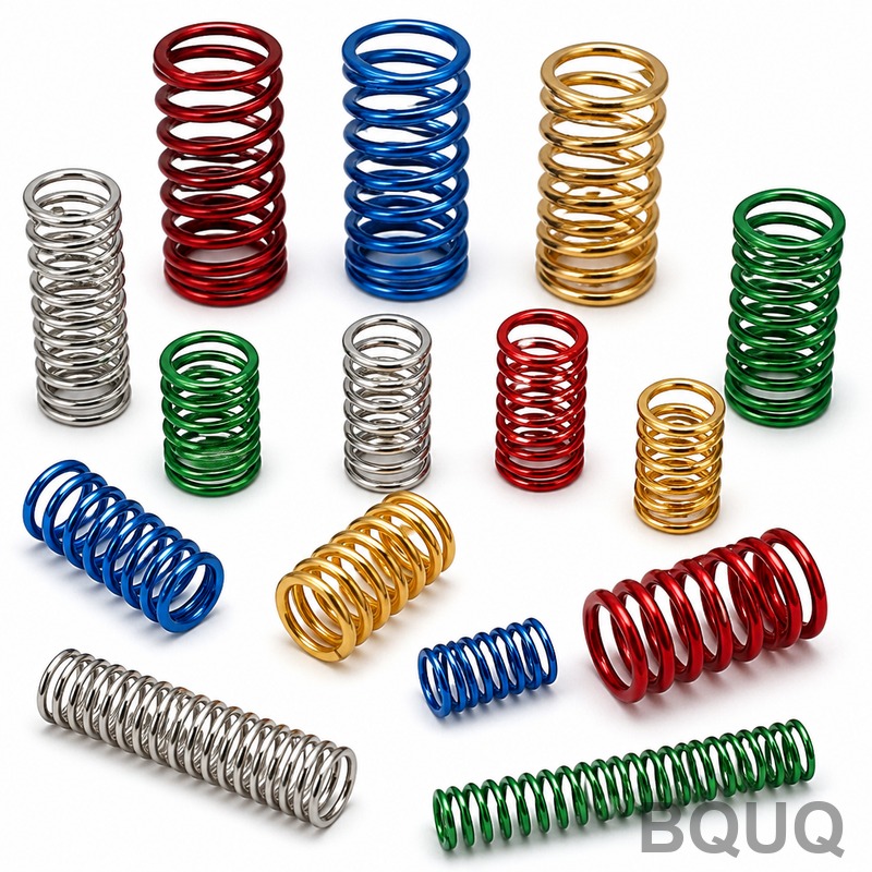
The theoretical spring rate for a round wire helical compression spring is calculated using the following formula:
k = (G x d^4) / (8 x D^3 x Na)
Where: k = spring rate (N/mm) G = shear modulus of material (MPa) d = wire diameter (mm) D = mean coil diameter (mm) Na = number of active coils
The shear modulus is a material property that represents its stiffness under torsion. For common spring materials, the values are well established. Music wire (ASTM A228) has a shear modulus of approximately 79,300 MPa, while stainless steel 302 (ASTM A313) has a value of about 69,000 MPa. Oil-tempered chrome silicon wire (ASTM A401) offers a shear modulus of 79,300 MPa with higher fatigue resistance.
Consider a concrete example: a compression spring made of music wire with a wire diameter of 2.0 mm, a mean coil diameter of 12.0 mm, and 8 active coils. Using the formula, the spring rate is calculated as follows:
k = (79,300 x 2^4) / (8 x 12^3 x 8) = (79,300 x 16) / (8 x 1,728 x 8) = 1,268,800 / 110,592 = 11.47 N/mm
This theoretical value serves as the design baseline, but actual production springs will show minor variations due to manufacturing tolerances. At BQUQ, we typically hold wire diameter to plus or minus 0.02 mm, mean diameter to plus or minus 0.15 mm, and active coils to plus or minus 0.25 turns, which results in a calculated rate tolerance of roughly plus or minus 4% before testing.
Measuring Actual Spring Rate on Production Parts
Theoretical calculations are essential for design, but the actual spring rate must be verified on finished parts. The measurement process uses a compression tester that applies a controlled force and measures deflection with a linear encoder. The spring is compressed to a specified preload height, then further compressed to a test height, and the force difference divided by the travel distance gives the actual rate.
For example, a spring designed with a rate of 20 N/mm might be tested between 30% and 70% of its total deflection range. If the force at 30% deflection is 150 N and the force at 70% deflection is 350 N, the measured rate is (350 - 150) / (0.7L - 0.3L) where L is the maximum deflection. If L equals 25 mm, the rate is 200 N / 10 mm = 20 N/mm, confirming the design.
The test environment matters. Temperature affects spring rate because the shear modulus changes with temperature. For music wire, the shear modulus decreases by approximately 2% when temperature rises from 20°C to 100°C. For this reason, precision springs destined for high-temperature applications should be tested at their operating temperature. Stainless steel 302 maintains more stable properties up to 300°C, while Inconel X-750 can operate at 600°C but costs roughly four times more per kilogram than music wire.
| Spring Material | Shear Modulus MPa | Max Operating Temp C | Relative Cost Index | Typical Rate Tolerance |
| Music Wire A228 | 79,300 | 120 | 1.0 | plus or minus 5% |
| Stainless 302 A313 | 69,000 | 300 | 1.8 | plus or minus 4% |
| Chrome Silicon A401 | 79,300 | 250 | 2.2 | plus or minus 3% |
| Oil Tempered A229 | 79,300 | 150 | 1.2 | plus or minus 5% |
| Inconel X-750 | 77,200 | 600 | 4.5 | plus or minus 3% |
Factors That Affect Spring Rate in Production
Wire diameter is the dominant factor in determining spring rate because it appears to the fourth power in the formula. A change from 2.00 mm to 2.05 mm increases the rate by approximately 21%. This sensitivity means that wire diameter tolerance is the most critical control parameter in spring manufacturing. At BQUQ, we source wire with a tolerance of plus or minus 0.01 mm for high-precision springs, which adds about 8% to material cost but significantly reduces rate variation.
Mean coil diameter also influences the rate, but with a cubic relationship. A 1% increase in mean diameter results in approximately a 3% decrease in spring rate. During coiling, the mandrel size and wire tension must be tightly controlled to maintain consistent diameter. Our CNC coiling machines hold mean diameter to plus or minus 0.05 mm for wire up to 5 mm in diameter.
The number of active coils is determined by the total coils minus the end coils that are closed and ground. For compression springs with closed and ground ends, typically 1.5 to 2 coils are inactive. The exact number depends on the end configuration. If the end coils are not properly ground flat, the effective number of active coils can vary, causing rate inconsistency. Grinding the ends to a flatness of 0.05 mm or better ensures that the active coil count matches the design.
Spring Rate for Extension and Torsion Springs
Extension springs follow the same basic rate formula as compression springs, but they are manufactured with initial tension. This initial tension is the force required to begin separating the coils, and it adds to the force at any given extension. The rate calculation remains the same, but the total force is the sum of the initial tension and the rate multiplied by the extension distance. For example, an extension spring with a rate of 5 N/mm and an initial tension of 10 N will require 60 N to extend it 10 mm.
Torsion springs have a different rate unit, expressed in N-mm per degree of rotation. The formula for torsion spring rate is:
k = (E x d^4) / (64 x D x Na)
Where E is the modulus of elasticity, which is 206,000 MPa for music wire. Torsion springs wind tighter under load, and the mean diameter decreases as the spring deflects, which affects the rate. For precision applications, the rate should be calculated at the final deflected position rather than the free position. The acceptable tolerance for torsion spring rate is typically plus or minus 10% due to the higher sensitivity to friction and mandrel size.
Practical Recommendations for Engineers
When specifying spring rate, always define the operating range rather than just the free length. Springs are rate-linear only within their elastic range, typically between 15% and 85% of maximum deflection. Operating near solid height causes the rate to increase exponentially as the coils touch. Specify the force at two working heights, such as F1 at H1 and F2 at H2, and the rate will be calculated as the difference in force divided by the difference in height.
For high-volume production, request a rate tolerance of plus or minus 5% for general applications. Tighter tolerances are possible but will increase cost. A tolerance of plus or minus 3% increases the price by approximately 15%, while plus or minus 2% increases price by 30%. The cost increase comes from tighter wire selection, more frequent machine calibration, and 100% testing instead of sample inspection.
Material selection should be based on operating temperature, corrosion resistance, and fatigue life. For temperatures below 120°C with no corrosive environment, music wire offers the best value. For outdoor or washdown applications, use stainless steel 302. For high-cycle applications exceeding 100,000 cycles, consider chrome silicon or oil-tempered chrome vanadium, which offer better fatigue properties. Always request a material certificate to verify the actual chemical composition and mechanical properties of the wire batch.
When dealing with very high spring rates above 100 N/mm, consider alternative designs such as stacked springs or Belleville washers. A single spring with an extremely high rate may have a wire diameter so large that it is difficult to coil or may exhibit non-linear behavior. Stacked compression springs in series produce a lower combined rate, while springs in parallel produce a higher combined rate. This modular approach allows fine-tuning of the rate without custom tooling.
Common Spring Rate Calculation Mistakes
A frequent error is using the outside diameter instead of the mean diameter in the formula. The mean diameter is the outside diameter minus the wire diameter. Using the outside diameter will understate the spring rate because the mean diameter appears to the third power in the denominator. For a spring with an outside diameter of 14 mm and a wire diameter of 2 mm, the mean diameter is 12 mm. Using 14 mm instead of 12 mm reduces the calculated rate by over 30%.
Another mistake is counting all coils as active. For compression springs with closed and ground ends, two coils are inactive. For springs with closed but not ground ends, 1.5 coils are inactive. If the total coils are 10 and the ends are closed and ground, the active coils are 8. Using 10 instead of 8 in the formula will understate the spring rate by 20%.
Finally, do not confuse spring rate with stress. Spring rate is a geometric property, while stress is a material property. A spring can have a high rate but still be prone to fatigue if the stress at maximum deflection exceeds the material's endurance limit. Always calculate the stress using the Wahl factor to account for curvature and direct shear. For music wire, the recommended maximum stress at solid height should not exceed 45% of the tensile strength to ensure adequate fatigue life.
Conclusion and Engineering Support
Spring rate is a precise, calculable parameter that defines how a spring performs under load. The formula k = (G x d^4) / (8 x D^3 x Na) provides the theoretical rate, but production verification through force-deflection testing is essential to confirm the actual value. By controlling wire diameter, mean coil diameter, and active coil count, and by selecting the appropriate material for the operating environment, you can achieve the exact spring rate required for your application.
At BQUQ, we have 20 years of experience manufacturing precision springs, CNC machined components, metal stampings, and heat sinks. Our engineering team can review your spring design, recommend material and tolerance adjustments, and provide a production quote within 12 hours. Send your drawings or specifications to sc@bquq.com, or contact us on WhatsApp at +86 13713157787. Visit www.bquq.com to learn more about our spring manufacturing capabilities and quality control processes.


