
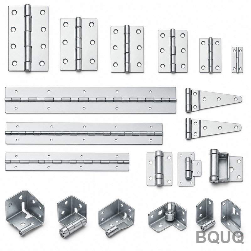
What Is Tolerancing in Metal Stamping? Typical Tolerances by Process and Material
Tolerancing in metal stamping is the system of specifying the allowable dimensional variation for a stamped part, typically expressed as a plus/minus value in millimeters or inches. In practical terms, it is the agreement between the engineer and the manufacturer defining how much a feature can deviate from the nominal design and still function correctly. Typical tolerances range from ±0.05 mm for precision fineblanking to ±0.50 mm for standard progressive die stamping, with material type, thickness, and feature geometry all shifting these baseline numbers.
What Is the Difference Between Standard and Precision Tolerancing in Metal Stamping?
Standard tolerancing, often called commercial or conventional tolerancing, applies to progressive die and transfer stamping operations that prioritize speed and volume. For parts up to 150 mm in length, commercial tolerances typically run at ±0.13 mm for hole diameters and ±0.25 mm for overall dimensions and bend locations. Precision tolerancing, by contrast, involves fineblanking, high-speed stamping with ground dies, or additional secondary operations like coining. Precision tolerances hold hole positions to ±0.025 mm and edge-to-edge dimensions to ±0.05 mm. The difference is not just die quality but also press rigidity, material flatness, and the use of in-die sensing; precision work requires a press with at least 40 percent more tonnage than the theoretical requirement to minimize deflection.
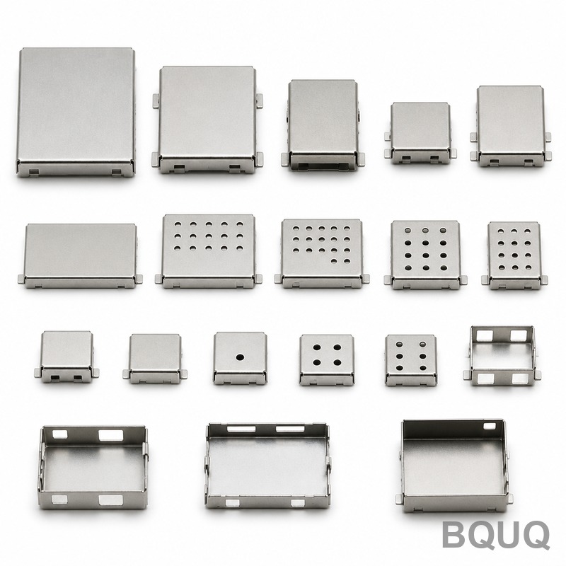
How Does Material Selection Affect Tolerancing Capability?
Material is the single largest variable in stamping tolerance because different metals exhibit different springback, elongation, and hardness behavior during shearing and bending. Cold-rolled steel (CRS) grades like SPCC and DC01 are the most predictable, allowing consistent tolerances of ±0.10 mm on formed features when thickness is between 0.5 mm and 2.0 mm. Stainless steel, particularly 304 and 316, has higher work-hardening rates, so bend tolerances widen to ±0.20 mm due to springback variation; it also requires 15 to 20 percent more press force. Aluminum alloys such as 5052 and 6061 are softer and tend to gall on the die, so hole tolerances typically relax to ±0.15 mm unless lubrication and die coatings like TiCN are upgraded. Brass and copper are highly ductile but have variable grain structure, so flatness tolerances are the most challenging, often requiring a secondary flattening operation to hold 0.10 mm over a 100 mm surface.
How Does the Stamping Process Determine Achievable Tolerances?
Each stamping process has a distinct tolerance envelope defined by its mechanics. Progressive die stamping, where a strip moves through multiple stations, holds general tolerances of ±0.13 mm but struggles with features that require tight relative positioning across stations. Fineblanking uses a triple-action press with a V-ring indenter to control material flow, achieving shear-zone smoothness of 100 percent and tolerances of ±0.025 mm on hole diameters. Deep drawing, used for cylindrical or box-shaped parts, is the least precise; wall thickness variation of ±0.10 mm and flange flatness of ±0.30 mm are typical because material thinning is difficult to predict. Four-slide stamping, for complex wire and strip forms, holds ±0.08 mm on bend angles but ±0.25 mm on spring-loaded dimensions. High-speed stamping above 400 strokes per minute introduces thermal growth in the die, so tolerances must be opened by 0.02 to 0.05 mm compared to the same die run at 200 spm.
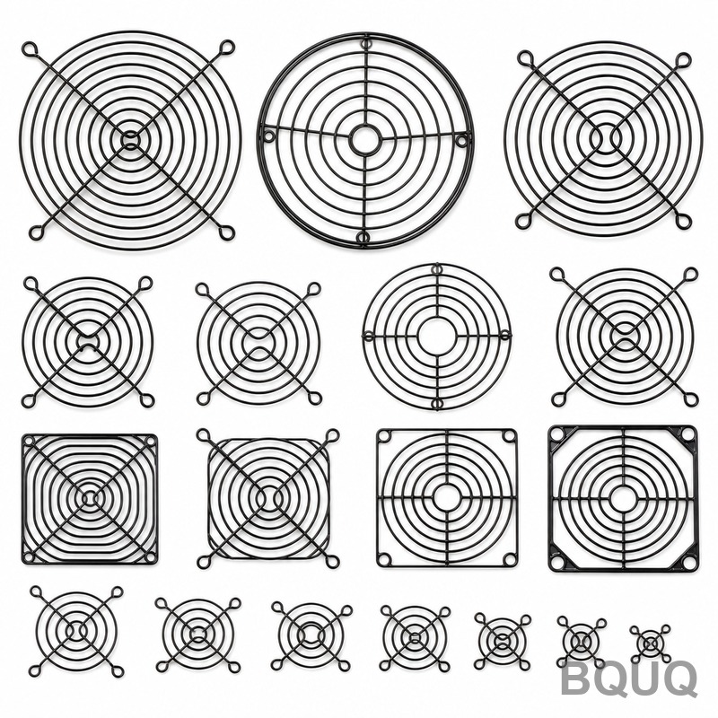
What Are the Typical Tolerance Values for Common Stamped Features?
The table below provides baseline tolerance values for common features in metal stamping, based on BQUQ’s production data over the last 20 years. These figures assume a part size under 100 mm and material thickness of 1.0 mm to 1.5 mm; deviations require adjustments.
| Feature Type | Progressive Die Stamping | Fineblanking | Deep Drawing | Four-Slide Stamping |
| Hole diameter | ±0.13 mm | ±0.025 mm | ±0.20 mm | ±0.10 mm |
| Hole-to-hole center distance | ±0.15 mm | ±0.05 mm | ±0.30 mm | ±0.12 mm |
| Overall length (bend to bend) | ±0.25 mm | ±0.08 mm | ±0.50 mm | ±0.20 mm |
| Bend angle (degrees) | ±1.0 degree | ±0.5 degree | ±1.5 degrees | ±0.75 degree |
| Flatness over 100 mm | 0.30 mm | 0.10 mm | 0.50 mm | 0.40 mm |
| Burr height on cut edge | 10% of material thickness | 3% of material thickness | 15% of material thickness | 8% of material thickness |
Which Tolerancing Standard Should You Use for Your Stamped Part?
You should use the ISO 2768 standard for general tolerances when the part is for global export, and the ASTM E29 standard when shipping to the United States. ISO 2768-m (medium class) gives linear dimensions of ±0.10 mm for sizes up to 30 mm, ±0.20 mm for 30 to 120 mm, and ±0.30 mm for 120 to 400 mm, which is adequate for most enclosures and brackets. For automotive stamped parts, the AIAG PPAP and IATF 16949 standards require statistical process control (SPC) with a Cpk index of 1.67 or higher on critical features, which means the tolerance band must be at least 5 times the process standard deviation. For precision connectors and terminals in electronics, the IPC-7527 standard governs stamping tolerances; it recommends ±0.02 mm for terminal width and ±0.05 mm for pitch in high-density connectors. If no standard is specified, BQUQ defaults to ISO 2768-m and prints the standard on the drawing for clarity.
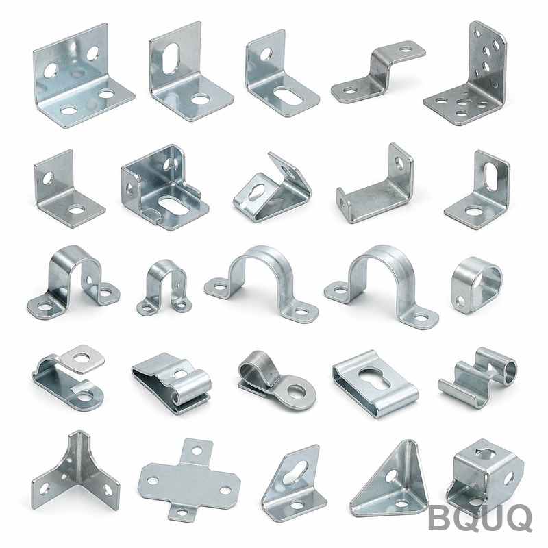
How Does Part Size and Thickness Change Tolerance Values?
Part size and material thickness interact to set a practical tolerance floor. For every additional 25 mm of part length, overall dimensional tolerances must typically widen by 0.05 mm because of thermal expansion in the die and material feed variation. Material thickness also sets a physical limit: the minimum hole diameter that can be stamped is roughly equal to the material thickness for carbon steel, and the tolerance on that hole is ±0.05 mm plus 5 percent of the thickness. For example, a 2.0 mm thick stainless steel plate will have a minimum hole diameter of about 2.0 mm, with a tolerance of ±0.15 mm. Thicker materials above 3.0 mm generate more shear force, causing die deflection that adds 0.02 mm of tolerance error for every 10 mm of die width. Conversely, very thin materials below 0.3 mm are prone to edge stretching and buckling, so tolerances on formed features must be increased by 30 percent.
When Should You Use GD&T Instead of Standard Tolerances for Stamping?
You should use Geometric Dimensioning and Tolerancing (GD&T) when the stamped part interfaces with other components at multiple points, such as a mounting bracket for a motor or a heat sink clip. GD&T, governed by ASME Y14.5, allows you to define position tolerance at maximum material condition (MMC), which can increase the actual allowable manufacturing tolerance by up to 0.10 mm without affecting function. For example, a hole pattern with a positional tolerance of 0.10 mm at MMC is easier to produce than a traditional coordinate tolerance of ±0.05 mm, because the bonus tolerance from hole size variation is applied. GD&T also clarifies datums, which is critical for stampings that are located by their edges and holes; without it, the inspector may use a different reference, causing rejection of good parts. However, for simple parts with only one or two critical dimensions, standard tolerances are faster to inspect and do not require a CMM (coordinate measuring machine), reducing inspection cost by 40 percent.
FAQ
What Is the Tightest Tolerance Achievable in Metal Stamping?
The tightest practical tolerance in production metal stamping is ±0.01 mm on a single feature, achievable only in fineblanking or high-speed precision stamping with carbide dies and a controlled environment. This level is reserved for features like connector terminals or bearing cages, and it requires material thickness under 1.0 mm and a press with 0.005 mm ram repeatability. For most parts, a realistic limit is ±0.025 mm, which balances cost and capability.
How Much Does Tighter Tolerancing Increase the Cost of a Stamped Part?
Moving from a commercial tolerance of ±0.13 mm to a precision tolerance of ±0.05 mm typically increases the unit price by 25 to 40 percent. This cost increase comes from slower press speeds (reduced from 300 spm to 150 spm), more frequent die maintenance (every 100,000 hits instead of 500,000), and higher inspection frequency (100 percent sorting instead of sampling). For a typical bracket costing 0.50 USD at commercial tolerance, the same part at precision tolerance would cost about 0.65 to 0.70 USD.
Which Material Gives the Most Consistent Tolerances in Stamping?
Cold-rolled steel in grades SPCC, DC01, or 1008/1010 gives the most consistent tolerances because of its uniform grain structure and predictable springback. It maintains ±0.10 mm tolerances on bent features over long production runs without die adjustment. In contrast, aluminum 6061-T6 and stainless steel 301 full-hard require frequent die compensation due to work hardening and thermal drift.
Can You Weld a Stamped Part and Still Hold the Original Tolerances?
Welding a stamped part will distort the local geometry, so the original tolerances cannot be held within 10 mm of the weld seam. For example, a 1.5 mm thick steel bracket that holds ±0.15 mm before welding may show 0.30 to 0.50 mm distortion after MIG welding. To resolve this, you must either design the weld locations away from critical surfaces or specify that critical dimensions are measured after welding, with a secondary coining or straightening operation to correct distortion.
When Do You Need to Specify a Surface Finish in Addition to Tolerances?
You need to specify surface finish when the stamped part is a heat sink, a contact, or a visible exterior component. Heat sinks for electronics require a surface roughness of Ra 1.6 micrometers or better on the mating face to ensure effective thermal transfer, which is achieved by a coining pass. Electrical contacts require a burr-free edge and a surface finish of Ra 0.8 micrometers to prevent arcing. These finishes are measured after stamping and add a secondary operation cost of 5 to 10 percent.
How Do You Inspect Tolerances on Stamped Parts in Production?
Production inspection uses a combination of hard gauges, optical comparators, and CMMs depending on volume and tolerance. For high-volume parts with tolerances above ±0.10 mm, go/no-go gauges are used at 100 percent for critical dimensions, with a CMM check every 2 hours. For precision tolerances below ±0.05 mm, parts are checked on a CMM at a frequency of one part per 50 pieces, and a vision system measures all hole positions in-line at full press speed.
What Is the Lead Time for a Stamped Part with Tight Tolerances?
A stamped part with tolerances of ±0.05 mm or tighter requires a lead time of 4 to 6 weeks for tooling, versus 2 to 3 weeks for commercial tolerances. The additional time covers die tryout with certified material, adjustment of the press parameters for springback compensation, and a first-article inspection report with SPC data. BQUQ can shorten this to 3 weeks if a similar die exists in our tool library.
Conclusion
Tolerancing in metal stamping is not a one-size-fits-all number; it is a function of process choice, material behavior, part geometry, and the inspection method you are willing to fund. For most commercial parts, ISO 2768-m with a baseline of ±0.13 mm is sufficient, but for functional interfaces, you must move to GD&T or fineblanking to achieve ±0.05 mm. The most cost-effective approach is to loosen tolerances where possible and tighten them only on critical mating surfaces, as this reduces die cost and press time significantly.
At BQUQ, our 20 years of stamping experience across CNC machining, metal stamping, springs, and heat sinks means we can advise on realistic tolerances before you finalize your drawing. We provide a 12-hour quoting service with immediate DFM feedback on tolerance risks. Send your design to sc@bquq.com or reach us on WhatsApp at +86 13713157787, or visit www.bquq.com to start your project.


