
Which Metal Stamping Processes Produce Reliable Electronics Terminals and Contacts?
For electronics terminals, contacts, and connector parts, precision metal stamping is the dominant manufacturing method because it delivers high-volume production with repeatable tolerances down to ±0.01 mm at costs as low as $0.005 per piece. Progressive die stamping, specifically, accounts for over 80% of all connector terminal production globally due to its ability to combine blanking, bending, coining, and plating in a single pass at speeds of 600 to 1,200 strokes per minute. This article details the material specifications, tolerance capabilities, cost structures, and quality protocols required for mission-critical electronic stampings, based on BQUQ’s 20 years of serving automotive, telecom, and consumer electronics clients from our Dongguan facility.
What Materials Are Best for Stamping Electrical Contacts and Terminals?
The selection of raw material dictates conductivity, spring force retention, and corrosion resistance. Copper alloys dominate because pure copper lacks the yield strength needed for spring contacts. Beryllium copper (C17200) is the premium choice for high-cycle connectors, offering a tensile strength of 1,200–1,400 MPa after heat treatment and conductivity of 22–25% IACS. For cost-sensitive applications, phosphor bronze (C5210) provides a balanced 8–10% IACS conductivity with excellent fatigue resistance at a 30–40% lower material cost than beryllium copper.
Brass (C2600) is used for non-spring terminals like power lugs where formability matters more than elasticity. For high-temperature environments (above 150°C), copper-nickel-silicon alloys like C7025 maintain strength without stress relaxation. Stainless steel (SUS301) is stamped for EMI shielding contacts, though its 3–4% IACS conductivity limits it to mechanical grounding roles. Plating is then applied—selective gold (0.76 µm) for signal integrity, tin (2–5 µm) for solderability, and palladium-nickel for wear resistance in automotive connectors.
How Tight Can Tolerances Be for Stamped Connector Parts?
Precision progressive dies achieve positional tolerances of ±0.01 mm on critical pitch dimensions and ±0.02 mm on formed bend radii. For terminal widths under 2 mm, BQUQ routinely holds burr height to less than 0.03 mm, which is essential to prevent arcing in high-voltage connectors. Flatness is controlled to 0.05 mm over a 25 mm length, and coplanarity of multi-pin connectors is held within 0.08 mm total indicator reading (TIR).
These tolerances are achieved through a combination of tungsten carbide die inserts (with 0.002 mm grinding accuracy), optical in-process gauging, and temperature-controlled stamping presses that maintain die temperature at 25°C ± 2°C. For comparison, standard metal stamping for brackets allows ±0.1 mm, making electronics stamping ten times more precise. It is critical to note that tolerance capability is directly linked to material thickness—for 0.1 mm thick phosphor bronze, tolerance of ±0.008 mm is achievable, while 0.5 mm thick brass allows only ±0.02 mm due to grain structure variations.
Which Stamping Process Is Best for High-Volume Terminals?
Progressive die stamping is the unequivocal answer for volumes exceeding 100,000 pieces annually. In this process, a continuous metal strip advances through a multi-station die, with each station performing a sequential operation: pilot hole piercing, profile blanking, bending, coining, and final cut-off. A 16-station die can produce a complete terminal every 0.05 seconds, yielding 1,200 parts per minute from a high-speed press.
For lower volumes (5,000–50,000 pieces) or prototype validation, four-slide (multi-slide) stamping is used because it eliminates strip carriers and allows complex 3D forms with a single tool. However, the tooling cost is 2–3 times higher per part than progressive stamping. Deep drawing is reserved for cylindrical connector housings, while fine blanking (with V-ring impingement) is specified when sheared edges must be 100% smooth for sliding contacts—achieving a shear surface of 100% versus 50–70% in conventional stamping. The choice ultimately depends on annual volume, geometric complexity, and required edge quality.
Why Do Contact Surfaces Require Strict Plating and Surface Finish Control?
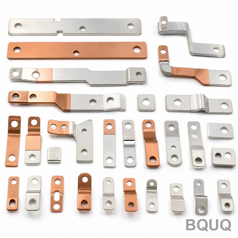
The functional interface of a terminal is its mating surface, where oxidation, porosity, or contamination creates electrical resistance and heat generation. Stamped contacts must achieve a surface roughness of Ra 0.4 µm or better on the contact area, which is ensured by polished die surfaces and the use of micro-etching before plating. Nickel underplating of 1–2 µm acts as a diffusion barrier, preventing copper migration through the gold topcoat.
Selective plating is a critical cost-saving technique—only the contact zone (typically 20–30% of the strip area) receives gold, reducing precious metal consumption by 60% compared to barrel plating. The plating thickness is verified by X-ray fluorescence (XRF) at 0.1 µm accuracy, and porosity is tested via nitric acid vapor exposure for 24 hours with zero corrosion spots allowed. For tin-plated contacts, the "tin whisker" risk is mitigated by controlling plating stress below 10 MPa and annealing at 150°C for one hour after plating.
How Much Does Tooling and Per-Part Cost for Electronics Stamping?
Tooling investment is the primary barrier to entry. A simple 8-station progressive die for a basic leaf contact costs between $8,000 and $15,000, while a 20-station die for a complex automotive terminal with multiple bends and a lance can reach $30,000 to $60,000. These costs include design, CAD simulation (using AutoForm for springback prediction), tungsten carbide inserts, and tryout on a production press.
Per-part pricing follows economies of scale: at 1 million pieces, a phosphor bronze terminal costs $0.008–$0.015 each; at 10 million pieces, the price drops to $0.003–$0.006. The table below provides benchmark pricing and parameters for common electronics stampings:
| Part Type | Typical Material | Thickness (mm) | Tolerance (mm) | Tooling Cost (USD) | Per-Part Cost at 1M pcs | Lead Time (weeks) |
| Simple battery contact | Brass C2600 | 0.20 | ±0.03 | $8,000 | $0.005 | 4 |
| Standard signal terminal | Phosphor bronze C5210 | 0.15 | ±0.02 | $15,000 | $0.009 | 6 |
| High-current power lug | Copper C1100 | 0.80 | ±0.05 | $22,000 | $0.018 | 8 |
| Automotive pin header | Beryllium copper C17200 | 0.25 | ±0.01 | $35,000 | $0.025 | 10 |
| Shield can (EMI) | SUS301 stainless | 0.10 | ±0.04 | $12,000 | $0.012 | 5 |
These figures assume a 5-year amortization of tooling, standard packaging (tape and reel), and domestic Chinese supply chain. Rush tooling (4-week delivery) adds a 25–30% premium.
When Should You Choose Stamping Over CNC Machining or Casting?
Stamping wins when the part has a uniform wall thickness under 3 mm, requires high volume (above 50,000 pieces), and can tolerate a slight burr on the cut edge. CNC machining is selected only for low-volume prototypes or when the geometry has undercuts that cannot be formed by a straight-pull die. Die casting is inappropriate for thin-wall contacts because porosity degrades electrical conductivity and mechanical ductility.
A practical rule of thumb: if the terminal has a length-to-thickness ratio above 10:1 and a bend radius of at least 1× material thickness, it is stampable. For very small parts (under 1 mm overall length), stamping remains viable down to 0.05 mm thickness, but tooling costs escalate by 50% due to the need for micro-punches with 0.02 mm diameters. Additionally, stamping offers the fastest cycle time—a single press can output more parts in one hour than a CNC shop can produce in one week.
What Quality Tests Are Mandatory for Stamped Electronic Contacts?
Every lot of stamped terminals must pass a suite of electrical and mechanical tests per IEC 60512 and EIA-364 standards. Contact resistance is measured using the four-wire Kelvin method at 10 mA and 20 mV, with a maximum allowable resistance of 10 mΩ for gold-plated contacts and 20 mΩ for tin-plated. Insertion and withdrawal force is tested at 150 cycles per minute—typical values range from 0.3 N to 2.0 N depending on the connector pitch.
Durability testing requires 500 to 10,000 mating cycles without exposing base metal or exceeding a 50% increase in contact resistance. Salt spray testing (5% NaCl, 35°C, 48 hours) verifies corrosion resistance, while a heat age test at 105°C for 250 hours checks for stress relaxation—a spring contact must retain at least 80% of its initial normal force. In-process SPC (statistical process control) monitors critical dimensions every 30 minutes, with CpK values above 1.33 required for release to production.
Can Stamping Achieve the Surface Finish Required for High-Speed Data Connectors?
Yes, but only with specialized secondary operations. For high-speed connectors (USB4, HDMI 2.1, PCIe Gen 5) operating above 10 Gbps, the stamped contact surface must have a roughness of Ra 0.2 µm to minimize signal reflection and insertion loss. This is achieved by adding a coining operation in the die, which compresses the surface under 500–800 MPa pressure, yielding a mirror-like finish without removing material.
The mating area also requires a precise radius—typically 0.05–0.10 mm—to ensure a defined contact point. This is formed by a rolling operation or by designing the die with an extra "ironing" station. For impedance-controlled connectors, the stamped signal pins are often encapsulated in a liquid crystal polymer (LCP) housing, where the stamping tolerance of ±0.01 mm ensures consistent dielectric spacing. It is worth noting that the stamping direction (grain orientation) affects high-frequency performance, so parts are always stamped with the grain perpendicular to the signal path to reduce eddy current losses.
FAQ
What Is the Minimum Order Quantity for Custom Stamped Terminals?
Most precision stamping suppliers, including BQUQ, set a minimum of 50,000 pieces for a new progressive die tool to amortize the tooling cost. For quantities from 5,000 to 50,000, we recommend a soft tooling approach using aluminum bronze dies, which costs 40% less but has a shorter die life of 500,000 strokes versus 5 million for carbide.
How Do I Choose Between Gold and Tin Plating for My Contacts?
Gold plating (0.76 µm minimum) is required for signal integrity in low-voltage circuits (below 1V) and high mating cycles (above 1,000), as it is inert and does not oxidize. Tin plating (2–5 µm) is suitable for power connections above 12V and fewer than 50 mating cycles, where the oxide film is broken by higher contact force.
What Is the Typical Lead Time for Stamped Connector Parts?
For a new tool, the lead time is 4–10 weeks: 2 weeks for design and simulation, 2–4 weeks for die manufacturing, and 1–2 weeks for sample approval and production ramp-up. Production quantities of 1 million pieces are typically shipped within 2 weeks after tool approval, with faster delivery available at a 15% premium.
Can Stamped Parts Be Used in Medical or Aerospace Applications?
Yes, but with tighter controls. Medical-grade terminals require ISO 13485 certification, and materials must pass USP Class VI biocompatibility tests. Aerospace connectors demand traceability to the heat number of the raw material and 100% X-ray inspection for cracks, which increases per-part cost by 20–30%.
How Does Springback Affect Stamped Contact Geometry?
Springback is the elastic recovery of metal after bending, which can alter a 90-degree bend angle by 2–5 degrees for high-yield-strength alloys like beryllium copper. Our engineering team compensates for this by over-bending the die angle and using finite element analysis (FEA) to predict the final geometry within 0.5 degrees of the target.
What Is the Maximum Part Size for Precision Electronics Stamping?
The practical limit for connector terminals is 100 mm in length and 50 mm in width, dictated by the press bed size and strip width. For larger EMI shields or battery frames up to 200 mm, we use a progressive die in a 250-ton press, but tolerances relax to ±0.05 mm due to thermal expansion of the larger die.
Why Is Grain Direction Important in Stamped Contacts?
Grain direction, which runs parallel to the rolling direction of the metal strip, affects bendability and fatigue life. Bending perpendicular to the grain allows a tighter bend radius (0.5× thickness) without cracking, while bending parallel to the grain requires a larger radius (1.5× thickness). For spring contacts, we orient the strip so the bending axis is perpendicular to the grain to maximize fatigue resistance.
Conclusion
Precision metal stamping remains the most efficient and economical method for manufacturing electronics terminals, contacts, and connector parts, provided the design accounts for material selection, tolerance capability, and plating requirements. By leveraging progressive die technology with carbide tooling and automated in-line inspection, you can achieve sub-0.01 mm tolerances and million-piece production at a fraction of the cost of machining. BQUQ combines 20 years of Dongguan-based manufacturing expertise with modern simulation tools to deliver stampings that meet IEC, EIA, and automotive standards.
For your next connector or terminal project, send your 2D drawings or 3D models for a free engineering review and quotation. Our team responds with detailed DFM feedback, tooling costs, and per-part pricing within 12 hours. Contact us at Email: sc@bquq.com, WhatsApp: +86 13713157787, or visit www.bquq.com to start your precision stamping project today.


