
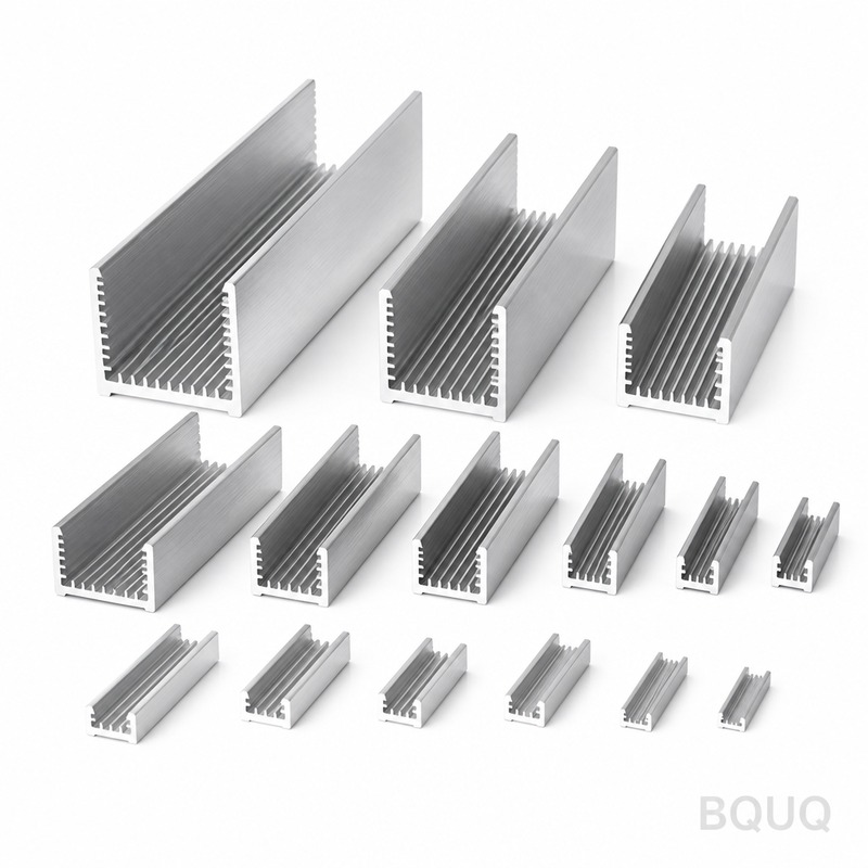
Why Does LED Heat Sink Design Matter for Lifespan and Performance?
The direct answer is that LED heat sink design dictates the junction temperature (Tj) of the LED chip, and every 10°C reduction in Tj can double the operational lifespan of the diode. Without a properly engineered thermal path, an LED rated for 50,000 hours can fail in under 10,000 hours due to accelerated lumen depreciation and catastrophic solder joint fatigue. Effective thermal management is not an accessory but the primary determinant of return on investment for any LED lighting system.
What Is the Maximum Safe Junction Temperature for Power LEDs?
The maximum allowable junction temperature for most high-power LEDs is 120°C, but continuous operation above 85°C triggers significant degradation. For example, a Cree XP-G3 LED rated at 1150 lumens at 25°C will drop to approximately 900 lumens if the Tj rises to 110°C. Industry standards from the Illuminating Engineering Society (IES) recommend maintaining a Tj below 85°C for a rated lifespan of 50,000 hours (L70). Operating at 105°C reduces the L70 rating to roughly 15,000 hours, a 70% reduction in useful life. Therefore, the thermal design target should be a thermal resistance from junction to ambient (Rth j-a) that keeps Tj below 85°C under maximum ambient conditions, typically 40°C to 50°C indoors.
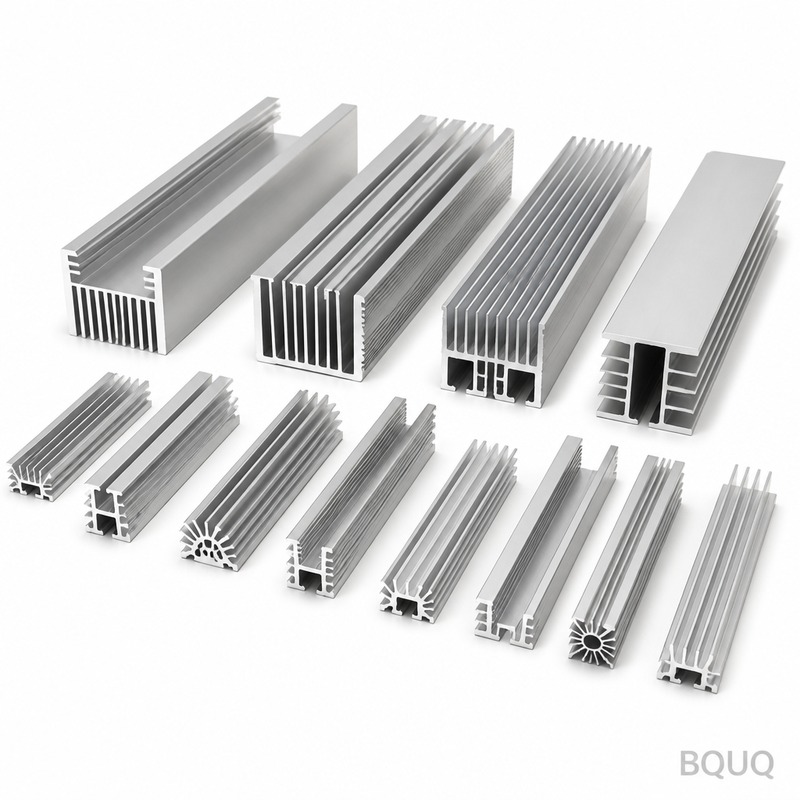
How Does Heat Generation Affect the LED Package and Solder Joints?
Heat generation within an LED is a direct consequence of electrical inefficiency; typically, 70% of input power is converted to heat, not light. This heat concentrates at the p-n junction and must flow through the die attach, the thermal pad, and the solder joints to reach the heat sink. When the coefficient of thermal expansion (CTE) mismatches between the LED package (usually 6 ppm/°C for ceramic) and the PCB (typically 17 ppm/°C for aluminum) are combined with high cycling temperatures, solder joint fatigue occurs. For a 3W LED, a poorly designed thermal path can cause a temperature rise of 30°C above ambient at the solder point, leading to micro-cracks after 5,000 thermal cycles. A proper heat sink limits the solder point temperature rise to under 15°C, extending the mechanical connection life beyond 50,000 cycles.
Which Heat Sink Material Offers the Best Thermal Performance per Cost?
The choice of material for a heat sink is a trade-off between thermal conductivity, weight, and manufacturing cost. The table below compares the three most common materials used by BQUQ in CNC machining and stamping processes.
| Material | Thermal Conductivity (W/mK) | Relative Cost per kg | Best Manufacturing Method | Typical Application |
| Aluminum 6063-T5 | 201 | 1.0 | Extrusion + CNC | Standard LED downlights |
| Aluminum 1050 (stamped) | 231 | 0.9 | Metal stamping | High-volume, thin fins |
| Copper C11000 | 398 | 3.5 | CNC machining | High-flux COB LEDs |
| Die-cast ADC-12 | 96 | 0.8 | Die casting | Complex, low-cost housings |
Aluminum 6063-T5 is the industry standard because it offers a good balance of thermal conductivity (201 W/mK) and low cost. For high-volume applications under 10W, stamped aluminum fins (1050 alloy) are preferable due to their low tooling cost, around $800 to $1,500, and a unit cost of $0.50 for a small stamped part. For LED arrays above 50W, copper inserts are often utilized, despite the cost being 3.5 times higher, because they reduce the spreading resistance by 40% compared to aluminum.
How Do Heat Sink Geometry and Surface Area Affect Cooling Efficiency?
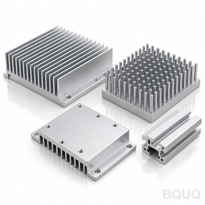
The primary function of a heat sink is to maximize the convective surface area while minimizing airflow resistance. A flat aluminum plate of 100mm x 100mm can dissipate about 10W at a 20°C temperature rise, but adding 20 fins of 20mm height increases the surface area from 0.01 m² to 0.09 m², enabling dissipation of 35W under natural convection. The fin spacing is critical; for natural convection, the optimal fin gap is between 6.5mm and 8mm to allow air to rise freely without boundary layer chocking. For forced convection (fans), fin gaps can be reduced to 3mm to 4mm. A rule of thumb is that the heat sink volume should be 5 to 10 cm³ per watt of heat dissipated for natural convection. For a 10W LED, an extruded heat sink with a volume of 70 cm³ and a surface area of 120 cm² will maintain a case temperature of 65°C in a 25°C ambient.
What Is the Impact of Thermal Interface Material (TIM) on Heat Sink Performance?
The thermal interface material (TIM) is the layer between the LED MCPCB and the heat sink, and it is often the bottleneck in the thermal path. A dry interface with air gaps has a thermal resistance of 0.1 to 0.2 °C/W, whereas a high-quality thermal paste with 5 W/mK conductivity reduces it to 0.02 °C/W. For a 10W LED, this difference accounts for a Tj reduction of 1.8°C, which translates to roughly 3,500 additional hours of lifespan. Phase-change materials are recommended for high-vibration environments, while thermal pads (1.0 W/mK) are suitable for simple assembly but require 20% more surface pressure to achieve proper contact. At BQUQ, we specify a minimum clamping pressure of 20 PSI for TIMs to ensure a bond line thickness of less than 50 micrometers.
How Much Does a Custom LED Heat Sink Cost to Design and Manufacture?
The cost of a custom LED heat sink depends heavily on the manufacturing process and production volume. For a stamped aluminum heat sink, the initial tooling cost is between $1,000 and $2,500, with a per-unit cost of $0.80 for volumes above 10,000 units. CNC-machined heat sinks involve no tooling charge but a higher per-unit cost; a typical 100mm diameter round heat sink with fins costs $4.50 per unit at 500 pieces, dropping to $2.80 at 2,000 pieces. Extruded heat sinks have a die cost of $2,000 to $3,500, with unit costs as low as $1.20 for a 100mm profile. For a complete solution including the LED holder and screws, engineering design fees range from $500 to $1,500, but BQUQ typically waives this fee for production orders exceeding 5,000 units.
When Should You Choose Forced Convection Over Passive Cooling for LEDs?
Forced convection (using a fan or active airflow) is necessary when the heat sink volume required for passive cooling exceeds the product enclosure limits. If the ambient temperature is above 50°C, such as in automotive headlights or industrial high-bay fixtures, passive cooling may require a heat sink of 200 cm³ for a 20W LED, which is often too bulky. In these cases, a smaller heat sink (100 cm³) combined with a 40mm fan can dissipate the same heat with a 10°C lower case temperature. However, fans introduce a reliability concern; a standard sleeve-bearing fan has a lifespan of 30,000 hours, which is less than the LED's 50,000-hour rating. For applications requiring a lifespan above 40,000 hours, passive cooling is mandatory, or a hybrid design with a redundant fan should be implemented.
FAQ
What Is the "Rule of Thumb" for Heat Sink Size per LED Watt?
For passive cooling, the heat sink volume should be approximately 8 to 10 cubic centimeters per watt of LED power. This ensures a temperature rise of about 25°C above ambient, which keeps the junction temperature below 85°C in typical indoor environments.
Can a Heat Sink Be Too Large for an LED?
Yes, an oversized heat sink is inefficient and costly, but it is not electrically harmful. The marginal benefit diminishes beyond a certain point; increasing surface area by 20% only improves thermal resistance by about 5% due to convection limitations.
How Does Ambient Temperature Affect the Required Heat Sink Design?
For every 1°C increase in ambient temperature, the LED's junction temperature increases equally, reducing lifespan by roughly 10%. If the ambient is 40°C instead of 25°C, the heat sink's thermal resistance must be reduced by 30% to maintain the same Tj.
Is Anodizing Necessary for Aluminum LED Heat Sinks?
Anodizing is not strictly necessary for thermal performance, as the oxide layer (if thin) adds only 0.01°C/W of resistance. However, it is recommended for corrosion resistance and to increase the emissivity from 0.1 (bare aluminum) to 0.9 (black anodized), which improves radiant heat transfer by 15% in enclosed fixtures.
What Is the Difference Between L70 and L50 Lifespan Ratings?
L70 indicates the time when the LED output has depreciated to 70% of its initial lumen output, while L50 indicates 50% depreciation. A heat sink that keeps Tj at 85°C may achieve L70 at 50,000 hours, but the L50 rating could extend to 70,000 hours. Most commercial warranties are based on L70.
Can Metal Stamping Produce Heat Sinks with Enough Surface Area?
Yes, stamped heat sinks can achieve an aspect ratio of 4:1 for fin height to thickness, but they are limited to fin heights of 15mm to 20mm. For higher performance, BQUQ uses a stamping-lamination process to stack thin sheets, creating a fin density that is 30% higher than extruded profiles.
Conclusion
The correlation between heat sink design and LED lifespan is absolute; a 10°C reduction in junction temperature doubles the operating life. Selecting the correct material, geometry, and manufacturing process is a balance of thermal physics and cost engineering. For a robust solution, prioritize a low thermal resistance path, verify the TIM application, and opt for passive cooling whenever the form factor allows. If you require a thermal simulation or a prototype quote for your LED heat sink, contact the engineering team at BQUQ for a response within 12 hours. Email us at sc@bquq.com or message via WhatsApp at +86 13713157787. Visit our website at www.bquq.com to download our thermal design guide.


