
Sheet metal bend allowance, k-factor and minimum radius rules, plus springback compensation, so flat blanks hit flange dimensions first time.
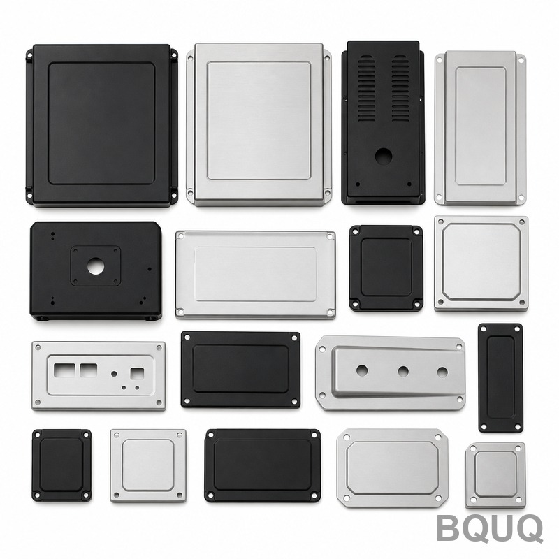
Sheet Metal Bending: Bend Allowance and Minimum Radius Rules
Bend allowance is the extra strip length consumed by a bend, and for a 90° bend in 1.0 mm steel with a 1.0 mm inside radius it adds roughly 1.5–1.7 mm of flat length compared with measuring to the sharp corner. Ignore it and every bent part comes out short or long by the same amount; calculate it and your flat blank unfolds to a part that hits its flange dimensions on the first try.
Every bent sheet metal part starts life as a flat blank. The question is how long that blank must be so that, after bending, the flanges land where the drawing says. Metal stretches and compresses through the bend: the outside surface stretches, the inside compresses, and somewhere through the thickness a neutral axis keeps its original length. Bend allowance is the length of that neutral axis through the bend arc, and it is the number that makes flat-pattern math work.
The Bend Allowance Formula
The standard formula for bend allowance treats the bend as an arc of the neutral axis. For a bend angle A in degrees, inside radius R, and material thickness T, with the neutral axis at a distance k×T from the inside surface:
BA = (π / 180) × A × (R + k × T)
The k-factor is the ratio that locates the neutral axis. It is not a constant — it moves outward as the bend gets tighter relative to thickness, because more of the material deforms. For air bending of common materials, k typically runs 0.30–0.45; 0.33 is a common starting value for sharpish bends and 0.4–0.5 for generous radii in thinner material.
| Bend condition | Typical k-factor |
|---|---|
| Sharp bend, R/T near 0.5–1 | 0.30–0.35 |
| Standard air bend, R/T ~1–2 | 0.35–0.40 |
| Generous radius, R/T > 2 | 0.40–0.45 |
| Hemming / bottoming operations | 0.45–0.50 |
The takeaway: pick a k-factor close to your real bending method and material, because a 0.1 error in k on a part with several bends multiplies into visible flange error. When in doubt, bend test coupons and measure — one test strip is cheaper than a scrap batch.
Bend Deduction: What the Shop Actually Uses
Shops often work with bend deduction (BD) instead of allowance: the amount to subtract from the sum of the outside flange dimensions to get the flat length. For a 90° bend, the outside dimensions measured to the theoretical sharp corner double-count the bend region, so both the allowance and the corner geometry must be backed out. The relation is BD = 2 × (R + T) − BA for 90° bends.
| Material and setup | Bend allowance for 90° (R = 1×T) | Bend deduction (90°) |
|---|---|---|
| 1.0 mm steel, R1.0, k 0.40 | ~1.6 mm | ~2.8 mm |
| 1.5 mm steel, R1.5, k 0.40 | ~2.4 mm | ~4.2 mm |
| 2.0 mm aluminum 5052, R2.0, k 0.42 | ~3.3 mm | ~5.5 mm |
| 0.8 mm stainless 304, R0.8, k 0.38 | ~1.3 mm | ~2.3 mm |
Values are typical for air bending and vary with tooling and material temper — treat them as starting points, not gospel. The important habit is consistency: use the same k-factor and method for the whole part, and confirm against the supplier's bend tables, since a press brake and a stamping die bend slightly differently.
Minimum Bend Radius: The Cracking Limit
The minimum inside radius exists because the outside surface of a bend stretches, and every material has a limit beyond which it cracks. As a rule of thumb, mild steel and aluminum bend fine at an inside radius of one material thickness; harder and less ductile materials need more. Bending parallel to the rolling direction is riskier than bending across it, because the rolled grain structure splits more easily.
| Material | Minimum inside radius (typical, × thickness) |
|---|---|
| Mild steel (SPCC, cold rolled) | 0.5–1.0× |
| Stainless 304, annealed | 1.0–1.5× |
| Aluminum 5052-H32 | 1.0–1.5× |
| Aluminum 6061-T6 | 1.5–2.5× (bends poorly, watch direction) |
| Brass (soft) | 0.5–1.0× |
| High-carbon / spring steel | 2–4× (often impractical, use forming) |
If the design needs a sharper inside corner than the material allows, options are limited: switch to a more ductile temper, add a coining or bottoming step that redistributes strain, or accept a small inside radius that is actually produced with a groove or relief. Spring-tempered material above roughly 1.5–2× hardness simply does not bend well — it springs back so far that the process becomes a fight. That is when forming and stamping thinking replaces plain press braking.
Springback: The Angle That Fights Back
Every bend springs back elastically when the press releases. Low-carbon steel springs back roughly 0.5–2°, aluminum a bit more, and high-strength or spring-tempered alloys 3–10° or more. The shop compensates by over-bending: the punch angle is set sharper than the target, or the die is designed with springback compensation built into the tool steel.
| Material | Typical springback per 90° bend |
|---|---|
| Mild steel | 0.5–2° |
| Stainless 304 | 1–3° |
| Aluminum 5052 | 1–3° |
| Aluminum 6061-T6 | 2–5° |
| High-strength steel / spring temper | 3–10°+ |
Springback is not just an angle problem — it also relaxes the bend radius slightly, which shifts the neutral axis and changes the allowance. This is why stamped and brake-formed parts are developed empirically: the die or the bend program is adjusted against measured parts until the angle repeats. For drawn or tightly toleranced bends, our sheet metal forming work at BQUQ treats springback compensation as part of tool design, not an afterthought.
Practical Flat-Pattern Rules
Two habits keep bent parts consistent. First, bend the flanges in an order that does not trap the part: the last bend must be reachable by the tooling. Second, keep bend lines away from holes and cutouts — a hole closer than about 2.5× thickness from a bend line distorts into an oval as the metal flows. Add relief notches at the ends of bends that run into an edge, or the corner tears.
| Rule | Minimum |
|---|---|
| Distance from hole edge to bend line | ≥ 2.5× thickness (typical) |
| Minimum flange length | ≥ 4× thickness, tooling dependent |
| Bend relief at edge | Small notch, depth ≥ bend radius + thickness |
| Consistency check | Confirm k-factor and BD with test bends |
Email sc@bquq.com or WhatsApp +86 137 1315 7787 with your PDF/DXF/STEP file. An engineer reviews it and replies with price, lead time and DFM notes on working days.
Frequently Asked Questions
Q: What is bend allowance in simple terms?
It is the length of material along the neutral axis inside the bend arc — the amount of flat strip the bend consumes. Add it to the straight sections of the part to get the correct flat blank length before bending.
Q: What k-factor should I use?
For air bending common steels and aluminum with an inside radius near one thickness, start at 0.35–0.40. Tighter bends shift it down toward 0.30, generous radii toward 0.45. Confirm with test bends for critical parts.
Q: What is the minimum bend radius for my material?
As a rule of thumb, mild steel and soft brass bend at 0.5–1.0× thickness inside radius; stainless 304 and 5052 aluminum need about 1–1.5×; 6061-T6 aluminum needs 1.5–2.5× and bends best across the grain. Hard, spring-tempered material is impractical to bend sharply.
Q: Why do my bent parts come out at the wrong angle?
Springback. The metal relaxes elastically after the bend — typically 0.5–2° for mild steel, more for aluminum and much more for high-strength alloys. Compensation is over-bending the punch or building springback correction into the die.
Q: Does bend allowance change between press braking and stamping?
Slightly. The k-factor and allowance depend on real tooling, clearance, and material temper, so the same nominal bend can differ between a press brake and a stamping die. Always develop flat patterns against the actual process, and confirm with the supplier's bend tables.
Related Articles
- stamped-spring-contact-materials — More from the BQUQ Metal Stamping engineering series.
- stamping-die-types-guide — More from the BQUQ Metal Stamping engineering series.
- metal-stamping-defects-guide — More from the BQUQ Metal Stamping engineering series.
Data Sources and Verification
Tolerances, cycle times and price ranges in this guide come from BQUQ production records at our Dongguan plant, where CNC machining (±0.005 mm), stamping, custom springs and heat sinks run under one roof. BQUQ is an ISO 9001:2015 certified factory; the certificate and batch inspection reports are available on request with every quotation.
Related Resources
- About BQUQ: an ISO9001-certified source factory in Dongguan running four production lines under one roof.
- Stamping and sheet metal: terminals, brackets and enclosures from the press line — stamped terminals and contacts, stamping brackets and mounts, sheet metal enclosures.
- Industry trends: manufacturing, material market, and sourcing analysis for buyers.
- Technical articles: engineering guides and process comparisons — more where this article came from.
- FAQ hub: quick answers on CNC, stamping, springs, and heat sinks.
- Case studies: real parts and real numbers from projects we engineered and delivered.
- Contact us: send your drawing and get a quote within 12 working hours.
Authored by the BQUQ Engineering Team. BQUQ is an ISO9001-certified source factory in Dongguan, China, running CNC machining, metal stamping, custom springs and heat sink lines under one roof. Send drawings to sc@bquq.com or WhatsApp +86 13713157787 for a quote within 12 working hours. www.bquq.com


