
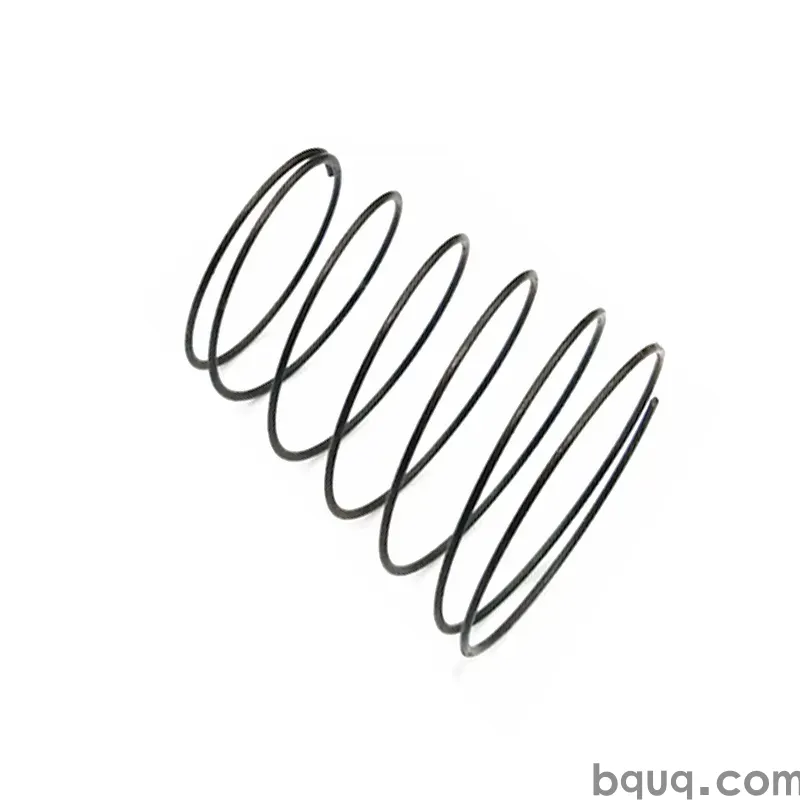
Springs for Battery and Shielding Contacts in Devices
Short answer: Battery and shielding contact springs are specified by contact force, not by wire diameter. For a typical AA/AAA cell holder, design 1.5–3.0 N of working force at the compressed height so the cell cannot rattle under 30 g vibration, and keep stress below roughly 40% of tensile so the spring does not relax over 5,000 mating cycles. For EMI shielding fingers, 0.3–0.8 N per finger with 0.5–1.0 mm working travel is common, plated with 0.05–0.1 µm gold over 1–3 µm nickel. BQUQ machines and winds these contacts in one Dongguan ISO9001 factory and returns a quote in 12 working hours.
Why contact springs behave differently from ordinary springs
A normal compression spring is judged on load at a given length. A contact spring is judged on something else: whether the electrical path stays stable while the mechanical path moves. That single difference reshapes almost every design decision.
Three failure modes dominate field returns on contact springs:
1. Force decay. The spring relaxes, the contact pressure drops, and contact resistance climbs. On a battery terminal this shows up as intermittent shutdowns; on a shield it shows up as a rise in radiated emissions during EMC retest.
2. Fretting corrosion. Micro-motion at the contact interface wears through plating, exposes base metal, and builds an insulating oxide film. Tin-plated contacts are especially vulnerable; gold is the standard defence.
3. Mechanical set. The spring is compressed past its elastic limit during assembly or a drop event and never returns to free height.
All three are governed by the same variables: material, stress level, plating system, and the geometry of the contact point. Get those four right and the contact spring becomes one of the most reliable parts in the product.
The force window is narrower than you think
Too little force and the contact resistance is unstable. Too much force and the mating feature — often a thin stamped battery clip or a plastic rib — deforms. For small consumer devices, the practical window is usually:
| Application | Working force per contact | Working travel | Typical wire / strip |
|---|---|---|---|
| AA / AAA cell negative terminal | 1.5–3.0 N | 1.5–3.0 mm | 0.5–0.8 mm music wire or 301 SS |
| Coin cell (CR2032) clip | 0.8–1.5 N | 0.5–1.2 mm | 0.3–0.5 mm 301 stainless |
| Board-to-board battery connector | 0.5–1.2 N | 0.3–0.8 mm | 0.2–0.4 mm beryllium copper |
| EMI shield finger (per finger) | 0.3–0.8 N | 0.5–1.0 mm | 0.1–0.2 mm 301 / 304 stainless |
| Shield gasket, continuous | 5–20 N per 10 mm | 0.5–1.5 mm | 0.1–0.15 mm stainless strip |
These are indicative ranges for handheld and small-enclosure electronics, not absolutes. A device that sees 50 g drop loads needs more preload; a device with a plastic housing rib needs less.
Which material should you choose for battery contacts?
Battery contacts live in a hostile little environment: galvanic couple with the cell can, occasional electrolyte leakage, humidity, and thousands of insertion cycles. Material choice is a compromise between conductivity, springiness, and corrosion resistance.
| Material | Conductivity | Spring quality | Corrosion resistance | Best for |
|---|---|---|---|---|
| Music wire (ASTM A228) | Low | Excellent | Poor without plating | Cost-driven internal springs, plated |
| Oil-tempered / hard-drawn | Low | Good | Poor without plating | General purpose, high volume |
| Phosphor bronze | Moderate | Good | Good | Battery terminals, moderate current |
| Beryllium copper (C17200) | High | Excellent | Good | High-cycle, low-resistance contacts |
| 301 stainless, full hard | Low | Excellent | Very good | Shield fingers, clips, no plating needed |
| 304 stainless | Low | Moderate | Very good | Shielding where formability matters more |
For pure battery current paths, phosphor bronze and beryllium copper are the usual picks because they combine useful conductivity with real spring temper. For shielding, conductivity matters far less than the ability to hold force for years without corroding, so full-hard 301 stainless is the workhorse — it can be used bare or with a thin nickel underplate.
If your contact also carries current and must survive salt spray, beryllium copper with nickel-plus-gold plating is the safest combination, at the highest cost. A common middle path is phosphor bronze with 1–2 µm nickel and 0.05–0.1 µm gold.
Plating: where most contact problems are actually born
Plating is not decoration; it is the electrical interface. Three rules cover most cases:
- Nickel underplate first. 1–3 µm of nickel stops copper or iron from diffusing into the gold layer and gives the gold something hard to sit on.
- Gold thickness follows cycle count. 0.05 µm handles roughly a few thousand mating cycles in a clean, low-force application. For high-cycle or harsh environments, 0.3–0.8 µm is normal. Hard gold (cobalt or nickel hardened) resists wear far better than pure soft gold.
- Tin is cheap but not forgiving. Tin oxide is an insulator. Tin-plated contacts need high normal force and a wiping action to break through the oxide on every mating cycle. If your design has low force and no wipe, tin will eventually fail.
For shield fingers that are assembled once and never mated again, bare stainless or nickel-plated stainless is often sufficient and much cheaper.
Shielding contact springs: force, pitch and grounding
EMI shielding springs do a different job from battery springs. They must maintain a low-impedance ground path across a seam, at a frequency range that can run from a few hundred MHz to several GHz. The physics rewards three things: short ground paths, many contact points, and stable force.
Finger pitch and slot length
Shield fingers behave like a slot antenna array. The gap between fingers must be short relative to the wavelength of the highest frequency you need to attenuate. As a practical rule, keep finger pitch under about one-twentieth of the wavelength at the highest frequency of concern. At 1 GHz (300 mm wavelength), that means pitch below roughly 15 mm; most designs go much tighter, at 2–5 mm, because it also improves mechanical robustness.
Grounding continuity
A single finger carrying the whole shield current creates a high-impedance path. Design for multiple parallel fingers per seam, and make sure the shield can itself is rigid enough that the fingers are not doing structural work. Where a shield must also be removable, a formed strip gasket with a continuous wave profile gives more contact points than discrete fingers.
Compression set and relaxation
Shield fingers are usually compressed once at assembly and left for the product's life. That makes stress relaxation the dominant risk. Keep working stress at or below about 35–40% of the material's tensile strength, and consider a stress-relief bake after forming. Shot peening the tension side of the finger is a proven way to raise fatigue life where the shield is repeatedly opened, such as during service access.
How do you specify a contact spring so the factory gets it right?
Most contact spring problems trace back to an incomplete drawing. Give the supplier these seven data points and you remove nearly all ambiguity:
1. Free height and working height (not just "compressed length").
2. Load at working height, with tolerance — typically ±10% for contact springs.
3. Maximum travel / solid height so the spring is never over-compressed during assembly.
4. Material and temper, or an explicit statement that material is supplier's choice.
5. Plating system with thickness for each layer, and which surfaces are plated.
6. Cycle life and environment (indoor, humid, salt spray, temperature range).
7. Contact geometry — flat pad, radius, or point contact, and the mating surface finish.
For stamped contact springs, add the strip thickness tolerance and the direction of the grain relative to the bend. Bending across the grain cracks high-hardness stainless; bending with the grain is far more forgiving. This is the same class of problem described in our guide to springback compensation in formed parts — the material fights you, and the tool has to be built to expect it.
Tolerances you can actually hold
At BQUQ, CNC-machined spring tooling and contact pins hold ±0.005 mm on critical features. Wound and formed springs are a different story: force tolerance of ±10% and free-length tolerance of ±0.3 mm are realistic for small contact springs, and tightening beyond that raises cost sharply because it demands 100% force sorting.
| Feature | Typical achievable | Notes |
|---|---|---|
| Wire diameter | ±0.01 mm | Governed by wire supplier |
| Free length (small spring) | ±0.3 mm | ±0.15 mm with sorting |
| Load at working height | ±10% | ±7% with 100% testing |
| Plating thickness, gold | ±20% of nominal | XRF verified |
| Finger pitch, stamped strip | ±0.05 mm | Tool-dependent |
| Angularity of finger | ±2° | Affects contact point location |
Design pitfalls that show up in production
Pitfall 1: designing to solid height. If the spring reaches solid height during a drop test, the coils touch, the force spikes, and something else in the assembly breaks. Leave at least 15–20% travel margin.
Pitfall 2: ignoring the mating surface. A gold-plated spring pressed against a bare copper pad creates a galvanic pair. Plating both sides of the interface, or choosing a compatible pair, matters more than the spring itself.
Pitfall 3: single-point contact on a shield. One finger per seam is a design error, not a cost saving.
Pitfall 4: no allowance for plating thickness in the force calculation. A 3 µm nickel plus 0.5 µm gold layer on a 0.15 mm finger is roughly a 5% thickness change — enough to shift force measurably on stiff, short fingers.
Pitfall 5: choosing tin to save cost on a low-force contact. Covered above, and it is the most common avoidable failure in consumer electronics.
Where a contact spring also acts as a latch or a mechanical detent, the design becomes a combined spring-and-clip problem. Our notes on initial tension in extension springs cover the preload side of that calculation, which is often the difference between a clip that holds and one that rattles.
Prototype to production: what to expect
Contact springs are usually needed fast, in small quantities first, then in volumes that justify a progressive die. A workable path:
- Prototype (days): CNC-machined or hand-formed samples from the specified material, plated in small batches. Useful for fit and force verification, not for life testing.
- Pilot (1–2 weeks): soft tooling or a short-run die, with first-article inspection and force curves.
- Production: progressive die for stamped contacts, CNC coiler or CNC former for wire contacts, with in-process force sampling.
BQUQ runs four production lines in one Dongguan factory — CNC machining, metal stamping, spring winding and forming, and heat sink production — so a contact spring that needs a machined pin, a stamped clip, and a wound spring can be quoted and built as one package rather than three. MOQ is flexible, which matters when you need 500 pieces to validate a design before committing to a die. Quotes come back in 12 working hours.
For corrosion-critical contacts, the plating and passivation choices in our spring corrosion protection guide apply directly to battery terminals and shield fingers.
Frequently Asked Questions
Q: What force should a battery contact spring apply?
A: For AA and AAA cell holders, target 1.5–3.0 N at the fully inserted position. Coin cell clips usually need 0.8–1.5 N. The lower bound is set by contact resistance stability and vibration; the upper bound is set by the strength of the plastic rib or clip that reacts the load. Always specify load at working height, not free length.
Q: Is gold plating necessary on shielding contact springs?
A: Usually not. Shield fingers are often assembled once and never mated again, so bare or nickel-plated 301 stainless is adequate and much cheaper. Gold becomes worthwhile when the shield is opened during service, when the environment is humid or salty, or when contact resistance must stay below a few milliohms over many cycles.
Q: Why does my battery contact lose force over time?
A: Stress relaxation. The spring was likely designed above roughly 40% of the material's tensile strength, or it was compressed near solid height during assembly. Switching to a higher-temper material, reducing working stress, or adding a stress-relief bake after forming will usually fix it. Plating does not cause relaxation; it only reveals it.
Q: Can one spring do both battery contact and EMI shielding?
A: Occasionally, but it is a compromise. Battery contacts need conductivity and moderate force; shield fingers need many contact points and low, stable force. Combining them usually means over-designing one function. If space forces the merge, use beryllium copper with nickel-gold plating and design multiple contact points on the same formed part.
Q: What tolerance can you hold on contact spring force?
A: Plus or minus 10% of nominal load at working height is standard for small contact springs. Plus or minus 7% is achievable with 100% force testing, which adds cost. Free length is typically ±0.3 mm, and critical machined features on the mating pin or housing can hold ±0.005 mm on our CNC lines.
Related Resources
- About BQUQ and our four Dongguan production lines: /about/
- Custom compression springs for battery and contact applications: /compression-springs/
- Extension and custom springs for clips and latches: /extension-custom-springs/
- Torsion springs for detents and rotating contacts: /torsion-springs/
- Industry trends in connector and contact design: /industry-dynamics/
- Full technical article archive: /bquq-blog/
- Frequently asked questions: /faq/
- Case studies from source-direct manufacturing: /case/
- Request a quote in 12 working hours: /contact/
Authored by the BQUQ Engineering Team. BQUQ (Dongguan) runs CNC machining (±0.005 mm), metal stamping, custom springs, and heat sink production in one ISO9001 factory. Source-direct from Dongguan, China — quote in 12 hours: sc@bquq.com | WhatsApp +86 13713157787 | www.bquq.com


