
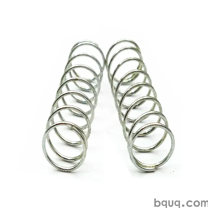
Contact Load in Springs for Connectors and Switches
Short answer: Contact load is the normal force a spring applies at the electrical interface — typically 0.2–1.5 N per contact for board-level connectors, 1–5 N for power terminals, and 0.5–3 N for tactile switches. It must stay high enough to break through oxide films and hold stable milliohm-level contact resistance, yet low enough to avoid wear, plating damage, and excessive insertion force. In practice you specify a window, not a single value — for example 1.2 N ±20% at rated deflection — then validate it with load testing at both ends of the tolerance stack. BQUQ machines and forms these springs in Dongguan to ±0.005 mm on CNC features and quotes in 12 working hours.
Why Contact Load Matters More Than Spring Rate in Electronics
In most spring applications, engineers start with rate. In connectors and switches, they should start with load.
A connector contact is an electrical device first and a mechanical device second. The spring's job is to generate a predictable normal force at the mating interface, because that force is what:
- Breaks through surface films. Copper alloys form oxide and sulfide layers within hours of exposure. A contact force of roughly 0.5 N or more is generally needed to fracture those films and establish true metal-to-metal contact. Below that, you are relying on tunneling conduction through a thin film, and resistance becomes unstable.
- Stabilizes contact resistance. Contact resistance falls steeply with increasing force at low loads and flattens out above roughly 1 N for typical gold-plated contacts. Operating in the flat region means small manufacturing variations do not translate into large resistance swings.
- Resists fretting and vibration. Micro-motion of a few micrometres at the interface causes fretting corrosion. Higher normal force reduces relative slip amplitude, which is why automotive and industrial connectors specify minimum forces rather than nominal ones.
- Survives thermal cycling. Differential expansion between housing, terminal, and spring changes deflection over temperature. A load window with margin absorbs that drift.
The counter-pressure is equally real. Too much force raises insertion force, wears gold plating, cold-welds soft tin contacts, and can deform the mating pin. For a multi-position connector, total insertion force scales with contact count — a 60-position connector at 2 N per contact needs 120 N of insertion force before friction factors, which is already uncomfortable for a field technician.
The design target is therefore a load window, defined at a specific deflection, with a defined tolerance, measured after the plating and forming operations that actually ship.
How Contact Load Is Specified on a Drawing
A well-written spring specification for an electronic contact contains four numbers, not one.
| Parameter | What it defines | Typical electronics value |
|---|---|---|
| Working deflection | Travel from free position to mated position | 0.15–0.60 mm |
| Contact load at working deflection | Normal force at the electrical interface | 0.3–1.5 N (signal), 1–5 N (power) |
| Load tolerance | Acceptable spread around nominal | ±15% to ±25% |
| Minimum load at end of life | Force after relaxation and cycling | ≥ 60–70% of initial nominal |
Two supporting values are also worth putting on the drawing: the free height (or free angle for torsion types) and the maximum stress at working deflection, expressed as a percentage of the material's yield or a target stress in MPa.
The reason to specify load rather than only dimensions is that load is the functional output. Two springs can measure identically on a comparator and deliver different forces because of wire diameter drift, coil count, heat-treat variation, or residual stress from forming. Load testing catches all of those at once.
For a deeper look at how rate and load interact across a family of springs, see spring rate vs load.
Signal versus power versus switch contacts
The three categories behave differently enough to warrant separate rules.
Signal contacts (board-to-board, FFC/FPC, fine-pitch) run 0.2–1.0 N. The dominant risk is not resistance but wear: low force plus vibration plus repeated mating cycles wears through 0.4–0.8 µm of gold. Many fine-pitch designs accept 0.3 N because the contact geometry uses a sharp crown or edge that concentrates stress and pierces films locally.
Power contacts run 1–5 N and sometimes higher. Here the driver is current density and heat. Higher force lowers constriction resistance, which lowers I²R heating at the interface. A 20 A blade contact at 3 N will run measurably cooler than the same contact at 1 N.
Tactile switches are a hybrid. The metal dome or cantilever must deliver a crisp snap with a defined actuation force (often 1.0–3.5 N) and a return force high enough to open the circuit reliably. Switch life is dominated by the ratio of actuation to release force and by the stress level in the dome.
Materials and Geometry: Where the Load Actually Comes From
Contact load is the product of stiffness and deflection. Both are set by material and geometry, and both are constrained by the electrical requirement.
Copper alloys dominate
| Material | Typical modulus | Conductivity | Where it fits |
|---|---|---|---|
| Phosphor bronze (C51000, C52100) | ~110 GPa | 15–20% IACS | General signal contacts, good fatigue life, low cost |
| Beryllium copper (C17200, C17510) | ~128 GPa | 22–60% IACS (aged) | High-cycle, high-force, small-deflection contacts |
| Brass (C26000) | ~110 GPa | 28% IACS | Low-cost, low-cycle, moderate force |
| Nickel silver | ~125 GPa | 5–10% IACS | Spring clips and shielding, not current-carrying |
| Stainless steel (301, 17-7PH) | ~190–200 GPa | <3% IACS | Retention clips, EMI fingers, non-signal springs |
Beryllium copper is the classic choice where force must be high and package size small, because it can be aged to very high yield strength while retaining useful conductivity. The trade-offs — including the regulatory and sourcing questions around beryllium — are covered in beryllium copper springs.
Geometry levers
Once material is fixed, the designer controls load through:
- Beam length and thickness. For a cantilever contact, load scales with thickness cubed and inversely with length cubed. A 10% thickness change moves load roughly 33%. This is why strip thickness tolerance matters more than most drawings acknowledge.
- Contact radius or crown. A sharper contact concentrates stress and lowers the force needed to break films, at the cost of higher local wear.
- Number of active coils in helical contacts, which sets rate linearly.
- Pre-load. Building in an initial deflection at assembly removes free play and makes the load-deflection curve start in its linear region.
Stress and relaxation
The limiting factor is usually not yield at assembly but stress relaxation over time and temperature. A contact held at 70–80% of yield at 85 °C will lose force continuously. Design practice for long-life connectors is to keep working stress below roughly 40–50% of the material's 0.2% yield strength at temperature, or to select an alloy with strong relaxation resistance such as aged beryllium copper or a high-performance phosphor bronze.
Manufacturing Tolerances That Move Contact Load
This is where a good design meets reality. Contact load is a stack-up, and every element contributes.
| Source of variation | Typical contribution to load spread | Control method |
|---|---|---|
| Strip thickness | ±3–8% | Incoming inspection, certified coil |
| Forming springback | ±5–15% | Tool compensation, in-die adjustment |
| Heat treat / age | ±5–12% | Furnace profile control, hardness checks |
| Plating thickness | ±1–3% | Bath control, XRF verification |
| Assembly deflection | ±5–10% | Fixture control, 100% load test |
| Measurement repeatability | ±2–5% | Gauge R&R, defined test speed |
Stacked randomly, these easily produce a ±20% load spread — which is exactly why ±20% is a realistic drawing tolerance and ±5% is not, unless you are prepared to 100% test and sort.
Two practical consequences:
1. Specify load at a deflection you can actually measure. If the drawing says "1.2 N at 0.4 mm" but the test fixture measures at free height, the number is meaningless.
2. Decide early whether you need 100% load testing. For safety-critical or high-volume automotive-adjacent parts, 100% automated load testing with pass/fail sorting is standard. For consumer electronics, statistical sampling with SPC on the forming process is usually sufficient. BQUQ's approach to this is described in spring load testing.
How Contact Load Is Measured
Three methods cover most production needs.
Force–deflection testing. A motorized stand drives the spring or contact to a defined deflection and records force. This gives the full curve, from which you read load at working deflection, rate, and any non-linearity. Speed matters: testing at 50 mm/min and 5 mm/min can give different results on plated or polymeric-coated parts.
Load-at-height testing. A simpler, faster check: compress to a hard stop and read the force. Suitable for high-volume sorting where only one point on the curve matters.
In-situ contact resistance testing. The most functionally honest test: mate the connector, pass a defined current (typically 100 mA max to avoid heating), and measure millivolt drop across the interface. This validates that the load window actually delivers stable resistance after plating, thermal cycling, and mating cycles.
A production-ready specification usually pairs a mechanical load test with a periodic resistance check, because a spring can pass the load test and still fail electrically if the contact geometry or plating is wrong.
Design Checklist for Connector and Switch Springs
Before releasing a drawing, confirm:
- Contact load is specified at working deflection, with a tolerance no tighter than the process can hold.
- Minimum end-of-life load is stated, accounting for relaxation at maximum operating temperature.
- Working stress is below the relaxation-safe threshold for the chosen alloy.
- Free height or free angle is specified with a tolerance that the forming process can meet.
- Material temper and grain direction relative to the bend line are called out.
- Plating is specified by thickness and type, with a note on the contact interface only.
- The test method, fixture deflection, and test speed are defined on the drawing or in a referenced spec.
- Mating cycle life and any thermal cycling requirement are stated.
For helical and coil-form contacts, the same discipline applies with rate substituted for beam stiffness — see compression springs for the standard geometry family, and extension custom springs where the contact is pulled rather than pushed. Rotary switch detents and multi-position contacts usually land in the torsion springs family.
Working With a Spring Manufacturer on Contact Load
The most common failure mode in sourcing electronic contact springs is a drawing that specifies dimensions but not function. The supplier then makes parts that measure correctly and fail in the field.
A short functional specification — load at deflection, tolerance, test method, and end-of-life minimum — removes most of that risk and lets the manufacturer choose the process route. It also lets them tell you honestly whether your target is achievable: a ±10% load window on a 0.15 mm-thick phosphor bronze cantilever with a 0.3 mm deflection is a very different proposition from the same window on a 0.5 mm-thick part.
BQUQ runs four production lines in one Dongguan factory covering CNC machining, metal stamping, custom springs, and heat sinks, which means contact springs can be stamped, formed, heat treated, and load-tested without leaving the building. CNC features hold ±0.005 mm where the contact geometry demands it. Quotes come back in 12 working hours, and MOQ is flexible enough for prototype and pilot builds.
Frequently Asked Questions
Q: What is a typical contact load for a board-to-board connector?
A: Most fine-pitch board-to-board and FFC/FPC connectors run 0.2–1.0 N per contact, with 0.4–0.6 N being a common nominal. Power contacts in the same family may run 1–5 N. The value depends on contact geometry, plating, and the number of mating cycles required. Always specify a window rather than a single number.
Q: How tight a contact load tolerance can a spring manufacturer actually hold?
A: For formed strip contacts, ±20% is routine and ±15% is achievable with good tooling and in-die adjustment. Tighter than ±10% generally requires 100% automated load testing and sorting, which adds cost. Helical compression springs can often hold ±10% on rate more easily than formed contacts hold ±10% on load.
Q: Does higher contact force always mean lower contact resistance?
A: No. Resistance drops steeply with force up to roughly 1 N for gold-plated contacts, then flattens. Beyond that point, extra force buys very little electrically while increasing wear, insertion force, and plating damage. The goal is to sit in the flat region with margin, not to maximize force.
Q: What causes contact load to drop over the life of a connector?
A: Stress relaxation in the spring material is the main cause, driven by temperature and the ratio of working stress to yield strength. Fretting wear and plating transfer at the interface also degrade performance. Keeping working stress below about 40–50% of yield at temperature, and choosing an alloy with good relaxation resistance, limits the drop.
Q: Can BQUQ produce contact springs to a specified load rather than just dimensions?
A: Yes. Send the working deflection, target load, tolerance, and test method, and BQUQ will select material and process route to hit it, then verify with load testing. Four production lines in one Dongguan ISO9001 factory cover stamping, forming, heat treatment, and testing. Quotes are issued within 12 working hours.
Related Resources
- About BQUQ and our Dongguan manufacturing footprint: /about/
- Compression springs for helical contact and retention applications: /compression-springs/
- Torsion springs for rotary switch and detent contacts: /torsion-springs/
- Extension springs for pull-type contact assemblies: /extension-custom-springs/
- Industry trends in connector and electronics manufacturing: /industry-dynamics/
- Technical articles on spring design and materials: /bquq-blog/
- Frequently asked questions about sourcing from BQUQ: /faq/
- Case studies from precision manufacturing projects: /case/
- Contact the engineering team: /contact/
Authored by the BQUQ Engineering Team. BQUQ (Dongguan) runs CNC machining (±0.005 mm), metal stamping, custom springs, and heat sink production in one ISO9001 factory. Source-direct from Dongguan, China — quote in 12 hours: sc@bquq.com | WhatsApp +86 13713157787 | www.bquq.com


