
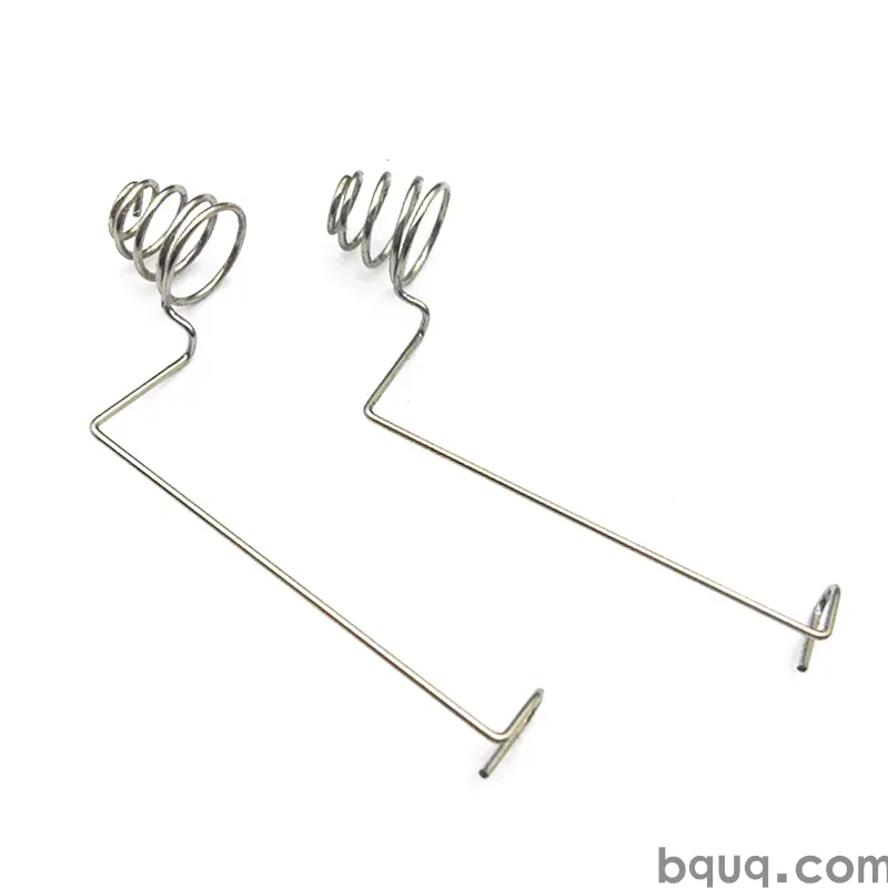
Stamped Fuse Holders and Clips: Design and Compliance
Short answer: A compliant stamped fuse holder is defined by three things — the right copper alloy, a contact force that stays inside the fuse blade's tolerance band over the full temperature range, and documented dimensional control. In practice, a 6.3 mm blade clip should hold roughly 8–20 N of insertion force and 4–12 N of retention force, with contact resistance typically under 5 mΩ. BQUQ stamps these parts on progressive dies in Dongguan to ±0.05 mm on formed features and ±0.005 mm on critical CNC-machined details, quotes in 12 working hours, and works to flexible MOQ so you can validate a design before committing to volume tooling.
Fuse holders look simple. They are not. A fuse clip is a spring, a current-carrying conductor, and a safety device at the same time, and it has to keep working after thousands of thermal cycles. Most field failures in fuse holders are not "the fuse blew" — they are loose clips, rising contact resistance, and heat that slowly anneals the spring out of its temper.
This article walks through the design decisions that matter for stamped fuse holders and clips, the compliance landscape you need to map before tooling, and the process controls that keep a good design good in production.
What does a stamped fuse holder actually do?
A stamped fuse holder performs four jobs simultaneously:
1. Mechanically locate the fuse so the blade or cartridge sits in a repeatable position.
2. Apply contact force through a spring geometry — usually a formed clip with two or four contact fingers.
3. Carry current with low resistance and low self-heating at the rated amperage.
4. Survive fault current long enough for the fuse to clear without the holder welding, arcing, or losing spring properties.
The third and fourth jobs are where stamped designs get interesting. A clip that measures fine on the bench can still drift out of spec once it is soldered to a PCB, potted in a housing, or cycled between -40 °C and +125 °C.
Blade clips vs. cartridge clips vs. bolt-in holders
The three common families behave differently:
| Family | Typical fuse | Contact style | Design focus |
|---|---|---|---|
| Blade clip (PCB or panel) | ATO/ATC, mini, maxi | Two-finger formed clip, 0.8–1.2 mm stock | Insertion/retention force, solderability |
| Cartridge clip | 5×20 mm, 6.3×32 mm | Ring or U-clip, 0.4–0.8 mm stock | Spring rate, axial alignment |
| Bolt-in / busbar holder | High-current strip fuse | Stamped terminal + bolted joint | Cross-section, torque, plating |
Blade clips dominate automotive and appliance work. Cartridge clips dominate electronics and instrumentation. Bolt-in holders are a different conversation — closer to a busbar design than a spring design.
Which copper alloy should a fuse clip be made from?
Material choice is the single highest-leverage decision. You are balancing conductivity, spring temper, stress relaxation, and cost.
| Alloy | Conductivity (% IACS) | Typical temper | Notes |
|---|---|---|---|
| C26000 brass | ~28% | H02/H04 | Cheap, easy to stamp, moderate spring; watch stress relaxation above 100 °C |
| C26800 / C27000 brass | ~27% | H02/H04 | Similar to C26000, good formability |
| Phosphor bronze C51000 | ~15% | H04/H08 | Excellent spring, good fatigue life, common for clips |
| Phosphor bronze C52100 | ~13% | H04/H08 | Higher tin, better spring and corrosion resistance |
| Beryllium copper C17200 | ~22% | TM00–TM04 | Best combination of conductivity and spring; higher cost and supply lead time |
| C70250 / C19010 (high-performance Cu alloys) | 40–60% | Various | Used where current density is high and space is tight |
For most 6.3 mm blade clips running under 30 A, phosphor bronze C51000 in H04 or H08 is the workhorse. If the ambient is hot and the current is high, move to beryllium copper or a high-performance copper alloy — not because brass is "bad," but because brass loses spring force faster under sustained thermal load.
Two rules that save projects:
- Do not specify brass for a clip that will sit above 100 °C continuously. Stress relaxation is not a manufacturing defect; it is a material property.
- Match plating to the mating blade. Tin-on-tin is fine and cheap. Tin-on-gold is a corrosion risk in humid environments. Silver plating lowers contact resistance but tarnishes and needs a defined cleaning and packaging spec.
How do you set contact force and insertion force targets?
Contact force is the number that determines whether your holder passes or fails. Too low and contact resistance climbs, causing local heating, which further relaxes the spring — a classic thermal runaway loop. Too high and the user cannot insert the fuse, or the blade deforms the clip on the first insertion.
Typical indicative targets for a 6.3 mm blade clip:
- Insertion force: 8–20 N per blade (lower for hand-inserted consumer parts, higher for automotive)
- Retention / withdrawal force: 4–12 N per blade
- Contact resistance: typically < 5 mΩ at rated current, measured as a voltage drop across the clip-blade interface
- Contact normal force: typically 3–10 N per contact finger, depending on finger count
These are starting points, not universal law. The correct targets come from the fuse standard your product is designed to, the rated current, and the ambient profile.
Why insertion force and retention force are not the same number
A formed clip is a cantilever spring. Insertion force includes friction on the lead-in ramps plus the force to open the fingers. Retention force is the spring force holding the blade once seated. A clip can have comfortable insertion and weak retention if the geometry is wrong — for example, a long lead-in ramp with a shallow seat.
This is why stamped terminal pullout force testing belongs in your design validation plan, not just in incoming inspection. Pull the blade out 10 times and measure force on the 1st, 5th, and 10th cycle. If the force drops more than about 15–20%, your geometry or material is marginal.
Designing the spring geometry
Practical geometry rules for a two-finger blade clip:
- Finger length: longer fingers give lower spring rate and more travel, but take more board area and are more prone to damage during handling.
- Finger width and stock thickness: these set the spring rate. Going from 0.6 mm to 0.8 mm phosphor bronze roughly doubles the force for the same deflection.
- Lead-in chamfer: 15–30° is typical. Too steep and insertion force spikes; too shallow and the blade misaligns.
- Over-travel stop: a formed feature that prevents the fingers from being bent past yield during insertion. This is one of the most commonly omitted details on first-pass designs.
- Anti-rotation features: tabs, dimples, or a formed shoulder that lock the clip into the housing or PCB footprint.
If your clip will be produced on a progressive die, the finger geometry also has to be stampable — no undercuts, no radii smaller than roughly half the stock thickness, and enough carrier material to keep the strip stable. Progressive die strip layout decisions made early will determine whether your elegant spring geometry is manufacturable at speed.
What tolerances can stamping realistically hold?
Stamped fuse holders are a mixed-tolerance part. Some features are cosmetic or clearance-driven; others directly control contact force.
| Feature | Typical achievable tolerance | Why it matters |
|---|---|---|
| Blank outline / carrier features | ±0.10 mm | General fit, not functional |
| Formed bend position | ±0.10 mm | Locates the clip in the housing |
| Formed feature height (finger gap) | ±0.05 mm | Directly sets contact force |
| Hole-to-hole pitch | ±0.05 mm | PCB or housing alignment |
| Critical machined detail (if required) | ±0.005 mm | CNC-finished features on the same factory floor |
| Burr height | ≤ 0.05 mm typical, tighter on request | Safety and dielectric clearance |
The finger gap is the tolerance that actually drives your force variation. A ±0.05 mm gap tolerance on a 0.6 mm-thick finger can still produce a meaningful force spread, which is why good clip designs include a force test in the control plan rather than relying on dimensional inspection alone.
For a deeper look at what is realistic across stamped features, see high-precision stamping tolerances.
Which compliance requirements apply to stamped fuse holders?
Compliance is not one document. It is a stack, and the stack depends on where the product is sold and what it is installed in.
Product safety standards
Fuse holders are usually evaluated as a component of a larger assembly, but the holder itself is often tested against:
- IEC 60127 series — miniature fuses and fuse holders, covering dimensional interchangeability, temperature rise, and dielectric strength for cartridge holders.
- UL 4248 — fuseholders, covering ratings, temperature rise, and mechanical endurance.
- UL 512 — for specific fuseholder constructions used in North American applications.
- IEC/EN 60335 / 62368 — end-product standards that impose creepage, clearance, and temperature-rise limits on the holder as installed.
Your customer's end-product standard is the one that ultimately governs. Ask for the creepage and clearance table and the temperature-rise limit before you finalize the clip outline — it is far cheaper than re-tooling.
Materials and environmental compliance
- RoHS / REACH — declarations on the alloy, plating, and any lubricant or anti-tarnish coating.
- Halogen-free — increasingly requested for enclosed electronics; affects plating and coating choices.
- Flammability — the metal clip is inherently non-flammable, but the housing it sits in may need a UL 94 rating, and the holder design must not compromise it.
Automotive and industrial overlays
If the holder goes into a vehicle, expect additional requirements around thermal cycling, vibration, and corrosion. These are typically imposed by the customer's own specification rather than a single universal standard. BQUQ holds ISO9001; where a customer program requires additional certification, that is handled at the program level, not assumed.
How do you validate a stamped fuse holder design?
A practical validation sequence, in order of cost:
1. Dimensional first article — full layout on the first parts off the die, including formed features.
2. Force testing — insertion and retention force across a sample, at 1st and 10th insertion.
3. Contact resistance / voltage drop — at rated current, on multiple samples.
4. Temperature rise — at rated current in the intended housing, at maximum ambient.
5. Thermal cycling — typically 500–1000 cycles between the low and high temperature limits, with force and resistance re-measured after.
6. Vibration and mechanical shock — if the application requires it.
7. Corrosion — salt spray or mixed flowing gas, depending on the environment class.
Steps 2 and 3 catch most design problems before you spend money on steps 5 through 7.
Common failure modes and their root causes
| Failure mode | Usual root cause |
|---|---|
| Retention force drops after cycling | Stress relaxation — material temper too low for the temperature |
| Contact resistance climbs | Insufficient normal force, contaminated or oxidized plating |
| Clip cracks at the bend | Bend radius too tight for the stock thickness or temper |
| Insertion force too high | Lead-in angle too steep, or over-travel stop missing |
| Blade misaligns | Formed position tolerance too loose, or no lead-in feature |
| Solder joint cracks on PCB clips | Thermal expansion mismatch, or clip geometry that loads the joint |
How does BQUQ produce stamped fuse holders and clips?
BQUQ (Dongguan) runs four production lines in one factory: CNC machining, metal stamping, custom springs, and heat sink production. For fuse holders and clips, that combination matters more than it sounds.
- Stamping produces the clip body, the holder bracket, and any mounting plate on progressive dies.
- Spring forming handles the contact finger geometry where a dedicated spring process gives better force control than a pure stamping form.
- CNC machining to ±0.005 mm covers critical details — locating bosses, machined seats, or tight-tolerance features that stamping cannot hold.
- Heat sinks are relevant when the holder sits next to a power device and the thermal design has to be considered together.
Quoting takes 12 working hours. MOQ is flexible, which means you can order a small validation batch, test it, iterate the die, and only then commit to volume. That is usually cheaper than tooling a design that has never been force-tested.
For stamped terminals and contacts specifically, see stamping terminals and contacts. For holder brackets and mounting hardware, see stamping brackets and mounts. And for the full stamping capability set, see custom metal stamping.
Frequently Asked Questions
Q: What material is best for a stamped fuse clip?
A: Phosphor bronze C51000 in H04 or H08 is the most common choice for blade and cartridge clips because it balances spring properties, fatigue life, and cost. Brass is acceptable for low-temperature, low-current applications but relaxes faster under sustained heat. For high current density or hot ambients, beryllium copper C17200 or a high-performance copper alloy is the better choice despite higher cost.
Q: How much insertion force should a 6.3 mm blade clip have?
A: For most applications, 8–20 N per blade is a reasonable starting window, with retention force of 4–12 N. Hand-inserted consumer parts sit at the low end; automotive and industrial parts sit higher. The correct target comes from your fuse standard, rated current, and ambient profile, so treat these as indicative and validate with force testing on real parts.
Q: Can a stamped fuse holder meet IEC 60127?
A: Yes, but compliance is evaluated on the installed assembly, not the bare clip. IEC 60127 covers dimensional interchangeability, temperature rise, and dielectric strength. You need the customer's creepage and clearance table and temperature-rise limit before finalizing the clip outline, because those constraints often drive the holder geometry more than the spring design does.
Q: Why does contact resistance rise over time in fuse clips?
A: The usual cause is stress relaxation: the spring loses normal force under sustained heat, contact pressure drops, and the interface resistance climbs. That local heating further relaxes the spring, creating a feedback loop. Choosing a higher-temper alloy, adding an over-travel stop, and validating with thermal cycling are the three most effective countermeasures.
Q: What tolerance can stamping hold on the finger gap?
A: A formed feature tolerance of ±0.05 mm is a realistic target on a well-maintained progressive die, and hole-to-hole pitch of ±0.05 mm is common. Because the finger gap directly sets contact force, the control plan should include a force test rather than relying on dimensional inspection alone. Where tighter control is needed, CNC-finished details can reach ±0.005 mm.
Related Resources
- About BQUQ and the Dongguan factory: /about/
- Custom metal stamping capabilities: /custom-metal-stamping/
- Stamped terminals and contacts: /stamping-terminals-contacts/
- Industry trends in stamping and connectors: /industry-dynamics/
- Technical articles and design guides: /bquq-blog/
- Frequently asked questions: /faq/
- Case studies: /case/
- Contact the engineering team: /contact/
Authored by the BQUQ Engineering Team. BQUQ (Dongguan) runs CNC machining (±0.005 mm), metal stamping, custom springs, and heat sink production in one ISO9001 factory. Source-direct from Dongguan, China — quote in 12 hours: sc@bquq.com | WhatsApp +86 13713157787 | www.bquq.com


